


TAC AB, 2003-07-01 0-004-7771-2 (GB), 25 (36)
TAC Xenta 400 I/O modules 4 Installation
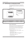
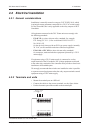
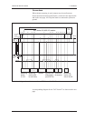
Connections
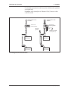
When cabinet mounting is used, jumpers may be used between
M (measurement neutral) terminal pairs, as shown in the figure below
and on the next page. All G0 points must be connected to protective
ground.
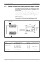
Basic circuit diagram for cabinet connections of TAC Xenta 451/452 I/O modules
1 2
G G0 U1 M U2 Y1 M Y2 B1 M B2 M
U3
G1 G G0
G G0 M
X
G G0 MX X1
PU
230
VAC
G
G0
N
1
2 1 2
M S
0 - 10
V
G G0 M S
R =500
Ω
R
min 1.5 mm
2
, max 2 m
Insulated
signal
ground rail
Cabinet
terminals
Cabinet
ground
rail
TAC Xenta 451/452 I/O module
Measuring
device
0–10 V
Measuring
device (with
its own trafo)
Actuator
Thermistor
(2 sensors)
Measuring
device, two-
wire 4–20 mA
Actuator with
differential in-
put (FORTA)
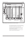
A corresponding diagram for the TAC Xenta 471 is shown on the next
page.