


24 (36), 0-004-7771-2 (GB) TAC AB, 2003-07-01
TAC Xenta 400 I/O modules 4 Installation
4.2 Electrical installation
4.2.1 General considerations
Installation is normally treated as category CAT III (IEC 664), which
in principle means permanent connection to a 230 V AC mains supply.
For the Xenta 400, this is only applicable to the relay outputs of the I/
O modules.
All equipment connected to the TAC Xenta units must comply with
the following standards:
- EN 60 742 (or other relevant safety standard; for example
ETL listing UL 3111-1, first version and CAN/CSA C22.2
No. 1010.1-92)
for the device(s) that provide an ELV-type power supply (normally
24 V AC) to the controller and other connected equipment.
- EN 61 010 or IEC 950 (or other relevant safety standard)
for computers, modems and other equipment powered by a 230 V
mains supply.
If equipment using a 230 V mains supply is connected to a relay
output terminal of the I/O modules, low-voltage equipment connected
to the other relay terminals of the controller must provide at least basic
insulation to all touchable parts.
We strongly recommend that switches are installed to make it possible
to separate external equipment when the relay output terminals control
equipment using a 230 V mains supply.
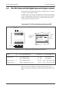
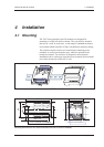
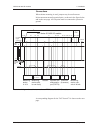
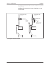
4.2.2 Terminals and units
• Mount the terminal part on a DIN rail.
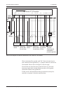
• Connect the cables to the correct terminals, see the figure below.
• Put the electronics part of the module on the terminal part.
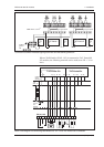
The terminal blocks of a TAC Xenta 400
~ 0
24 V AC
(19-40 V DC)
}
1 2 3 4 5 6 7 8 9 10
11 12 13 14 15 16 17 18 19 20
G G0 C1C2
Comm
}