


16 (36), 0-004-7771-2 (GB) TAC AB, 2003-07-01
TAC Xenta 400 I/O modules 3 Technical description
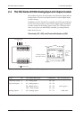
3.3 The TAC Xenta 421/422 Digital Input and Output module
The modules have four digital inputs and five digital outputs. The inputs
can also be used as pulse counters.
In addition, the TAC Xenta 422 is equipped with LED status indicators,
one for each digital input and manual override switches for the digital
outputs. The LED colors, red or green, are individually selectable, by
setting switches under the front cover.
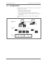
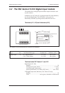
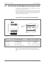
Terminals (421, 422) and Switches/Indicators (422)
4 DI Indi-
cators:
⇑ red
⇓ green
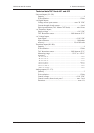
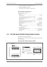
TAC Xenta 421/422 terminals and TAC Xenta 422 relay output switches and Indicators
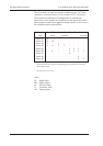
Type No. TAC Menta Block type Terminal ref. Ind./ Override(422)
Digital inputs 4 DI - Digital input or X1 - X4 red or green / –
CNT - Pulse counter X1 - X4 red or green / –
Relay outputs / 5 DO - Digital output or K1 -K5 green
1
/ ON-AUTO-OFF
Digital outputs DOPU - Digital pulse output K1 -K5 green
1
/ ON-AUTO-OFF
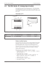
1 2 3 4 5 6 7 8 9 10
11 12 13 14 15 16 17 18 19 20
K1 K1C K2 K2C K3 K3C K4 K4C K5 K5C
G G0 C1C2 X1 M X2 X3 M X4
max 230 V AC
~ 0
24 V AC/DC
}
Comm
}
DO
TAC Xenta 422
ON
AUTO
OFF
2 3 4 5 1 2 3 4
DI
5 Relay output
Indicators
(green)
1
Note! The five output indicators always show the AUTO output
status, irrespective of the output override switch position (ON-AUTO-
OFF).