


28 (36), 0-004-7771-2 (GB) TAC AB, 2003-07-01
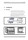
TAC Xenta 400 I/O modules 4 Installation
4.2.3 Cables
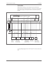
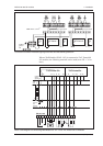
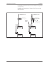
Power and Communication
G and G0 (Power supply):
G, min. cross-sectional area ...............................................0.75 mm²
G0 to TAC Xenta, min. cross-sectional area .......................1.5 mm²
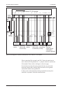
C1 and C2 (Network):
The TP/FT-10 system allows the user to wire the control devices
with virtually no topology restrictions.
Min. cross-sectional area ................................ 0.65 mm² (22 AWG)
The max. wire length in one segment depends on the type of wire
and the topology, see the table below.
The wires are not polarity sensitive, but must be a twisted-pair.
For more details, please refer to the ”TAC Xenta Network guide”.
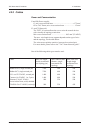
One of the following cable types must be used:
Cable Max. bus length, Max. node-to-node Max. total wire
doubly terminated distance, single length single
bus topology (m) terminated free terminated free
topology topology
Belden 85102, single twisted pair 2700 500 500
Belden 8471, single twisted pair 2700 400 500
UL Level IV 22AWG, twisted pair 1400 400 500
Connect-Air 22AWG, 1 or 2 pairs 1400 400 500
Siemens J-Y(st)Y 2x2x0.8 900 320 500
4-wire helical twist, solid, shielded
TIA568A Cat. 5 24AWG, twisted p. 900 250 450