


26 (36), 0-004-7771-2 (GB) TAC AB, 2003-07-01
TAC Xenta 400 I/O modules 4 Installation
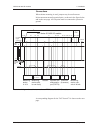
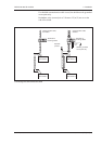
When connecting G0 to ground, each TAC Xenta unit must have its
own connection to the ground rail, i.e. jumpers cannot be used for the
G0 terminals. Please refer to the figure on the next page.
Several units may share the same ground rail, but every unit with
measuring inputs and/or analog outputs must have all its ground
connections with the same ground rail.
In other words, a discontinuation in the ground rail must not split a
controller or separate it from the connected units.
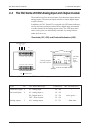
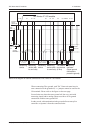
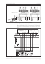
Basic circuit diagram for cabinet connections of TAC Xenta 471 I/O module
Measuring
device
Measuring
device (with
its own trafo)
Frequency
converter
(Signal ground
connected to
protective ground)
Out 24
VDC
4-20 mA
G G0 U1 M U2 U3 M U4 U5 U6 24VDC M U7
G G0 M S
0(4) - 20 mA
M S
0(4) - 20 mA
230
VAC
G
G0
N
M
S
M S
0 - 10
V
G G0 M S
0 - 10
V
min 1.5 mm
2
, max 2 m
Out 24
VDC
4-20 mA
Insulated
signal
ground rail
Cabinet
terminals
Cabinet
ground
rail
TAC Xenta 471 I/O module
Isolated
converter
Measuring
device
Measuring
device (with
its own trafo)
Two Measu-
ring devices
(2-wire)