


14
EN
Connections and Signal Flow
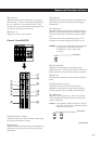
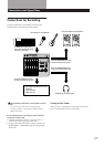
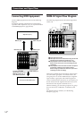
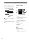
Connecting MIDI Equipment
Connect MIDI equipment as shown in the following
diagram.
For details regarding connections for synchronized
operation with a sequencer (etc.), see “Synchronization
with MIDI Equipment” (pages 52~56).
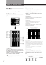
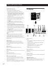
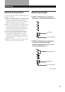
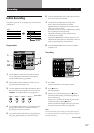
MDM-X4 Signal Flow Diagram
The following diagram shows the internal signal flow
of this unit.
1 Input external sounds.
2 The input sound is recorded after being mixed and
assigned to the respective group bus (1~4).
3 The playback sound from the recorder is input
back into the mixer (mix write recording, bounce
recording).
4 The playback sound from the recorder is output to
an external component, that adds an effect,
before being input back into the mixer (mix write
recording, bounce recording).
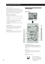
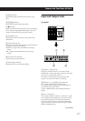
This unit’s 6 channel inputs and 2 stereo return inputs
are connected to group bus 1~4 and stereo bus L/R.
(For group bus 1~4 use the ASSIGN keys to assign the
input sound to a group bus. The channel signals are
always connected to the stereo bus. In cases where you
do not want to mix the signals to the stereo bus, lower
the faders for the respective channels to “0”.)
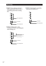
When monitoring, you can select group bus 1-2, group
bus 3-4, stereo bus, or TRACK 1~4 OUTPUT (CUE
bus).
For details on how to monitor, see “Monitoring
Example” (page 15).
Sequencer (etc.)
MIDI IN jack MIDI OUT jack
MIDI IN jack
MIDI OUT jack
MIDI THRU jack
External sound module (etc.)
To output the MIDI
signal input to this unit’s
MIDI IN jack directly to
other MIDI equipment.
1
2
3
4