


11
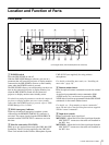
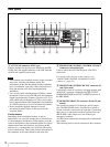
Location and Function of Parts
Note
For control of an LCD Data Projector VPL-PX15, use the
CONTROL S connectors instead of the PROJECTOR
CONTROL RS-232C connector.
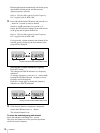
N SYSTEM TYPE selector
Can be set to positions 1-9, according to the speaker
configuration of the AV system being used. (Select
position 0 only when setting the system type using the
SRP-X500P Manager software.)
The setting becomes effective next time the power is
turned on. Thus, change the setting while the SRP-X500P
is turned off.
For details on the various system types, see “Selection of
system type” (page 19).
O IR OUTPUT MODE (remote programming)
button
Used to program an SRP-X500P command to an optional
remote commander with leaning capability.
For details on how to program an optional remote
commander, see “Programming a remote commander”
(page 28) and refer to the Operating Instruction supplied
with the remote commander.
P Microphone input adjustment section
+48V (48 V DC power supply) ON/OFF switches: Set
to ON to supply 48 V DC power to condenser
microphones connected to the MIC INPUT 1 to 4
connectors. These switches are factory-set to OFF.
Note
Before turning these switches, be sure to fully turn down
all input level controls and the LINE AV/RGB controls, or
turn off the unit.
TRIM (microphone input reference level adjustment)
controls: Set the reference level for signals input from
the MIC INPUT 1 to 4 connectors. The settable range
is –60 dBu to –30 dBu.
Notes
• A reference level cannot be set for signal input from
tuner units installed to the SRP-X500P.
• The TRIM controls treat their adjustable signal range as
two areas (one is between –60 dBu and –50 dBu and
another is between –49 dBu and –30 dBu) and because
of this, sound dropouts may be observed while adjusting
the reference level for the signal input from the
microphones. However, this is not a malfunction.
REF. (reference level) indicators: Light up yellow when
the audio signal whose level exceeds the reference
level is input to the MIC INPUT 1 to 4 connectors.
While the audio signal is input, adjust the TRIM
controls so that the REF. indicators light up yellow
intermittently.
FEED BACK REDUCER (howling suppressor)
buttons: Used to turn the howling noise reducing
function on or off, and to make settings for the
function. The buttons light up green when the function
is turned on.
For details on the settings, see “To suppress howling”
(page 22).
Q RS-232C indicator
Lights up green when the SRP-X500P and a PC or external
controller are communicating via the REMOTE RS-232C
connector.
R PROJECTOR ON/STANDBY POWER switch
Turns on the projector or the display monitor connected to
the SRP-X500P or sets the projector or the monitor to
standby status. Press the switch while it is lighted up red
(i.e., the projector or display monitor is in standby status)
to turn the projector or display monitor on. The switch
lights up green when the projector or the monitor is turned
on.
To turn off the projector or the monitor, keep pressing the
switch for more than 2 seconds. The switch flashes green
while the projector or the monitor cools off, and then lights
up red when the projector or monitor enters standby status.
Notes
• If you turn on the projector or display monitor or change
the input setting by operating it directly or by using the
remote commander supplied with it, the PROJECTOR
ON/STANDBY switch indication and actual status of
the projector or display monitor may become
unmatched.
• If you attempt to turn on the projector or display monitor
while it is cooling off, it may not respond. Turn it on
again after the projector or display monitor finishes
cooling off and enters standby status.