9
Location and Function of Parts
Location and Function of Parts
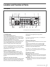
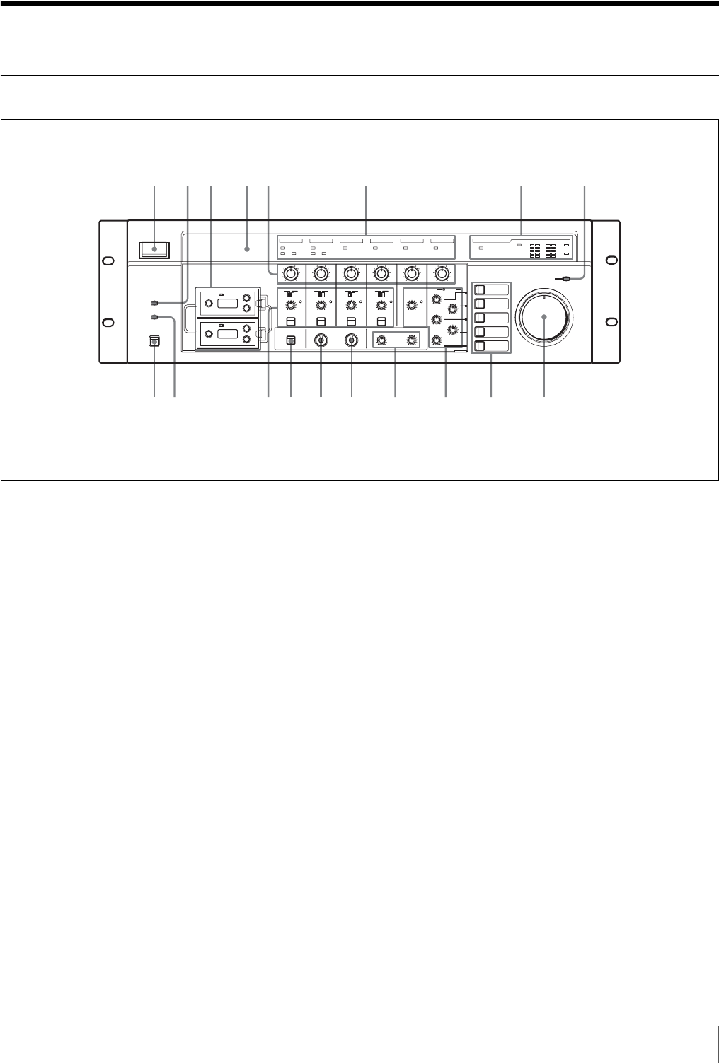
Front panel
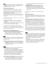
A POWER switch
Turns the SRP-X500P on and off.
With the SRP-X500P Manager software, you can set a
parameter that will cause the projector or display monitor
connected to the SRP-X500P to turn on or enter standby
status when the POWER switch is pressed.
The SRP-X500P is factory-set so that turning it on does not
turn on the connected projector or display monitor, but
when the SRP-X500P is turned off, the connected
projector or display monitor enters standby status.
For details on setting the parameter to make the connected
projector or display monitor turn on or enter standby
status when the POWER switch is pressed, refer to “SRP-
X500P Manager User’s Guide.”
B EMG (emergency) indicator
Lights up red when an emergency broadcast system
connected to the REMOTE PARALLEL connector is
activated. The output signals from the SPEAKERS CH
terminals and the LINE OUTPUT connectors are cut at
this time.
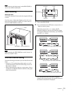
C Slots for tuner units (WL1/WL2)
Holds up to two optional tuner units (the WRU-806 UHF
Synthesizer Tuner Unit (not supplied) or the URX-M1
Tuner Unit included in the Wireless Microphone System
UWP-X1/X2 (not supplied)) for using wireless
microphones.
For details on installing tuner units, see “Installing the
tuner units” (page 14).
D Remote emitter/sensor
Point the optional remote commander towards the emitter/
sensor.
An optional programmable remote commander (RM-
AV3000 series, etc.) can be used to operate the SRP-
X500P after it has been programmed with the SRP-X500P
commands via the remote emitter/sensor.
For details, see “Programming a remote commander”
(page 28) and refer to the Operating Instructions supplied
with the remote commander.
E Input level controls
Rotate to adjust the input signal level.
MIC1/WL1: Adjusts the level of the signal input from the
MIC INPUT 1 connector or the tuner unit installed in
the WL1 slot.
MIC2/WL2: Adjusts the level of the signal input from the
MIC INPUT 2 connector or the tuner unit installed in
the WL2 slot.
1
9q
;
q
a
q
s
q
d
q
f
q
g
q
h
q
j
q
k
23 45 6 7 8
(In the figure above, the two blank panels are removed.)


