


25
Controls
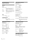
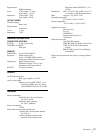
Specifications
Connector type: D-sub 25-pin, female
Recommended cable: Multi-core shielded cable for data
communications
Cable length: 50 meters (166 feet) or less
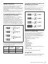
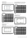
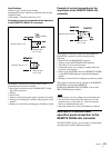
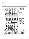
Examples of a circuit connection to the input pins
of the REMOTE PARALLEL connector
By making a contact, the following control can be
performed by an external controller:
• Input signal selection for the AV/RGB INPUT (video
and audio) connectors
•Muting
• Scene recall
• Volume control (turning the master volume up or down)
• Turning on or changing to standby of the projector or the
monitor
• Muting via control from an emergency broadcast system
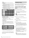
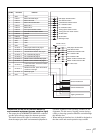
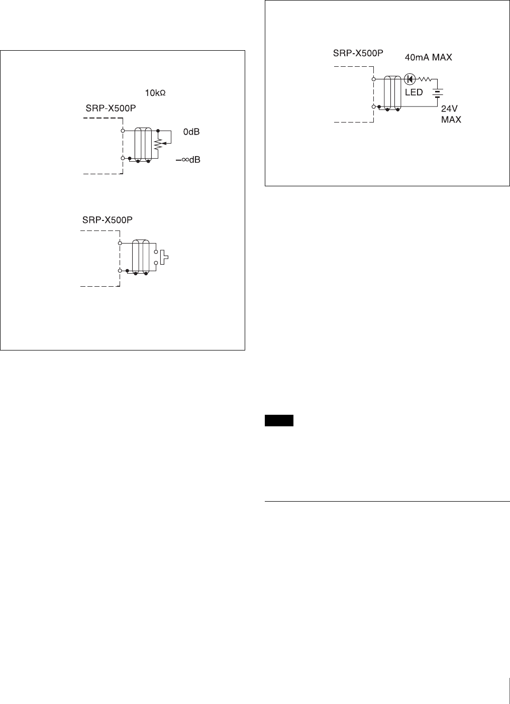
Example of a circuit connection to the
output pins of the REMOTE PARALLEL
connector
The trigger for turning on each pin of the REMOTE
PARALLEL connector can be selected from the
following:
• Status of the AV/RGB SELECT buttons
• Turning on the MASTER MUTING indicator
• The status of scene recall function
• Command to turn on or change to standby status the
projector or the monitor
• Status of the MASTER control and REMOTE FADER
on the SRP-X500P Manager (maximum/minimum/
muted)
• Muting via control from an emergency broadcast system
The trigger for each pin can be selected in the REMOTE
PARALLEL section of the REMOTE
PARALLEL/PROJECTOR CONTROL screen of the
SRP-X500P Manager software.
Notes
• Do not apply a reverse voltage across the output pins.
• Do not connect the shield of the remote wire or the
ground wire to a relay table, etc. This can cause the
device to malfunction and noise.
• Keep the remote wire away from dimmers or motors.
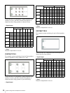
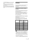
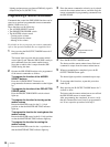
Example of a custom-made
operation panel connection to the
REMOTE PARALLEL connector
The SRP-X500P is factory set to connect a custom-made
operation panel with the following buttons:
Input pins (No.2 to 11)
B-curve variable
resistor
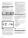
Input pins (No. 2 to 11)
GND pins (No.1,
12 to 14, 25)
GND pins (No. 1,
12 to 14, 25)
GND pins (No. 1,
12 to 14, 25)
Output pins (No.15 to 24)