23
Controls
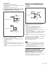
BACK REDUCER button to cancel the procedure,
turn down the SPEAKER OUT control, then try
again.
• Do not make a noise while the SRP-X500P is
scanning the frequency bands, as this may cause
error in detection.
• When you use the AGC (automatic gain control)
function, do the setting by using the SRP-X500P
Manager software before performing the procedure
above.
Controls
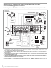
This section explains how to use the control connectors on
the SRP-X500P and how to program an optional
programmable remote commander with the functions of
the SRP-X500P.
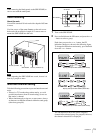
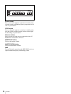
PROJECTOR CONTROL RS-232C
connector
The PROJECTOR CONTROL RS-232C connector can be
used to control a projector or display monitor equipped
with an RS-232C connector.
When the SRP-X500P is connected to a projector or
monitor through the PROJECTOR CONTROL RS-232C
connector, the power status (on or standby) and input
signal selection of the projector or monitor are linked to
those of the SRP-X500P.
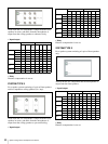
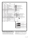
Set the PROJECTOR PROTOCOL selector in accordance
with the model of the projector or monitor, as indicated in
the following table.
The format of the video signal output to the
COMPONENT/RGB connector is factory-set to RGB
format. To change the setting, refer to the SRP-X500P
Manager User’s Guide.
Notes
• Use the cable whose specifications are matched with the
projector or monitor to connect the PROJECTOR
CONTROL RS-232C connector on the SRP-X500P with
the RS-232C connector on the projector or monitor.
• When controlling the projector from the SRP-X500P, be
sure to turn off the Smart APA function and Auto Input
Search function on the projector.
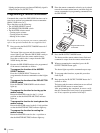
• If the projector or a display monitor is not included in the
table above, set the PROJECTOR PROTOCOL selector
Product model PROJECTOR
PROTOCOL
selector setting
RGB input
connector on the
projector or
monitor
VPL-CX85/80 1 INPUT A
VPL-PX35/40 2 INPUT D
VPL-FX51/50 3 INPUT A
VPL-PX11 4 INPUT A
VPL-PX32/31 5 INPUT A
FWD-50PX1 6 INPUT 1
PFM-42X1/V1 7 INPUT 1
PFM-42B2/B1 8 INPUT 1
PFM-50C1 9 INPUT A
Not applicable B-F -


