


18
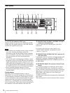
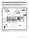
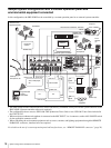
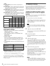
System Configurations and Speaker Connections
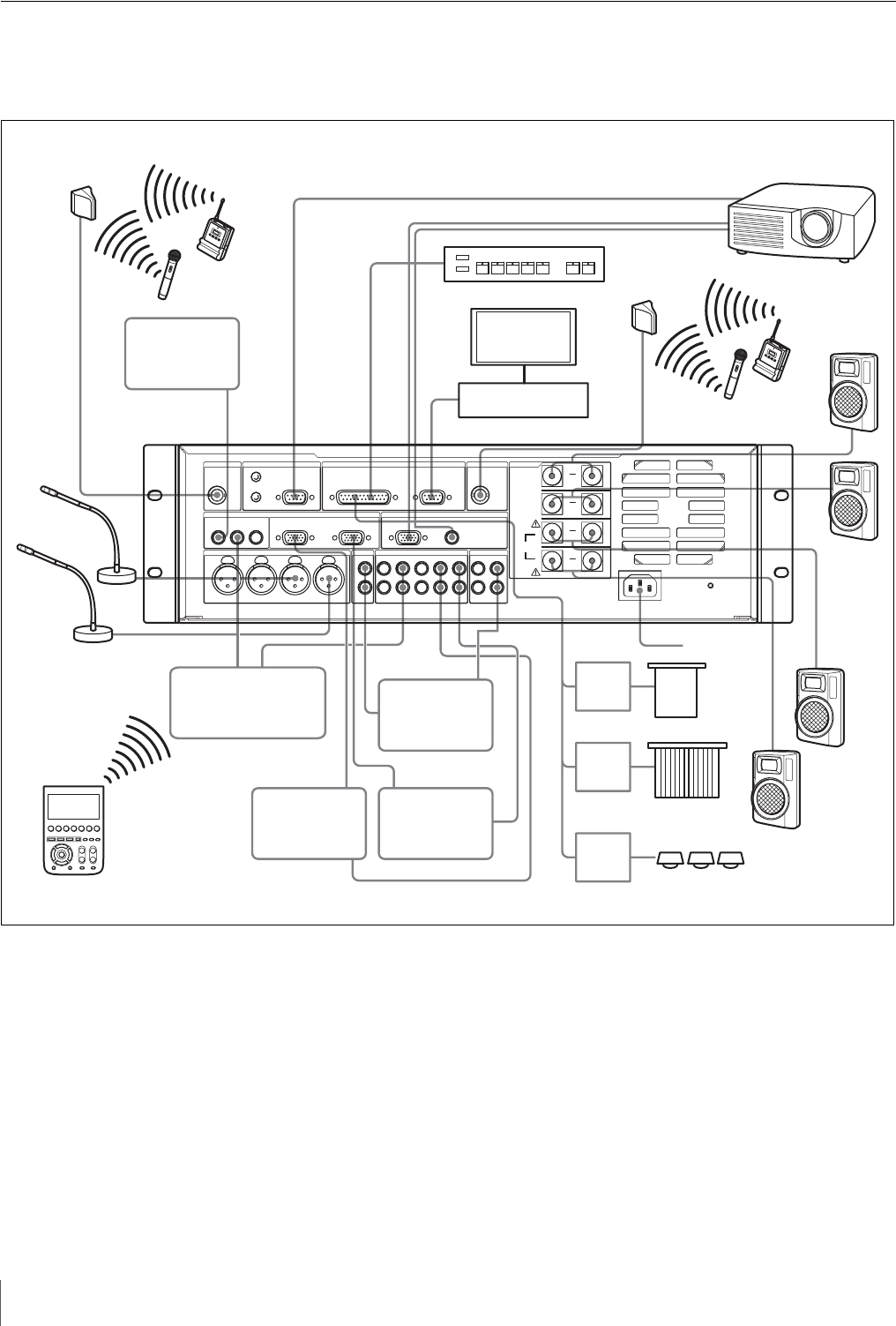
Sample system configuration with a custom operation panel and
environmental equipment connected
In this configuration, the SRP-X500P can be controlled by a custom operation panel or an external system controller.
• The SRP-X500P and the connected devices can be controlled by commands sent by an external system controller to the
SRP-X500P. (System controller software is required.)
• The configuration above uses two WRU-806 UHF Synthesizer Tuner Units or two URX-M1 Tuner Units included in
the UWP-X1/X2.
• When an electret condenser microphone is connected to the MIC INPUT 3 or 4 connector, set the +48V ON/OFF switch
for the applicable connector to ON.
• When controlling the environment equipment such as screen, curtains, and lighting equipment through the REMOTE
PARALLEL connector, interface boxes are required.
For details on the use of a custom operation panel and interface boxes, see “REMOTE PARALLEL connector” (page 24).
3#
3#
3#
3
#
3#
VIDEO OUT
INPUT
VIDEO OUT LINE OUT
RGB OUT
LINE OUT
RGB OUT
LINE
OUT
LINE OUT
LINE
IN
PROJECTOR CONTROL RS-232C
VCR , DVD player,
etc.
MD recorder
To power
source
Front
speaker
(R)
PC
Table-top
microphone, etc.
Programmable
remote
commander
PC
Front
speaker
(L)
AN-820 UHF
Antenna or the
supplied antenna
Wireless
microphone
Transmitter
Projector
Document
camera
Custom operation panel
Operation
terminal
External system controller
Wireless
microphone
Transmitter
AN-820 UHF
Antenna or the
supplied
antenna
Rear
speaker (L)
Rear
speaker (R)
Screen
Curtain
Lighting
equipment
I/F
BOX
I/F
BOX
I/F
BOX