24
Controls
to “0” and use the SRP-X500P Manager software to
make settings.
• For control of an LCD Data Projector VPL-PX15, use
the CONTROL S connectors instead of the
PROJECTOR CONTROL RS-232C connector. For
details, see “PROJECTOR CONTROL CONTROL S
IN/OUT connectors” (page 24).
PROJECTOR CONTROL CONTROL
S IN/OUT connectors
These connectors are for the control of the VPL-PX15
LCD Data Projector.
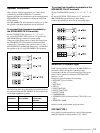
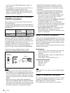
In order to control the VPL-PX15 with the SRP-X500P, set
the PROJECTOR PROTOCOL selector as described in the
following table.
When the SRP-X500P is connected to the projector
through the PROJECTOR CONTROL CONTROL S IN/
OUT connectors, the power status (on or standby) and
input signal selection on the projector are linked with those
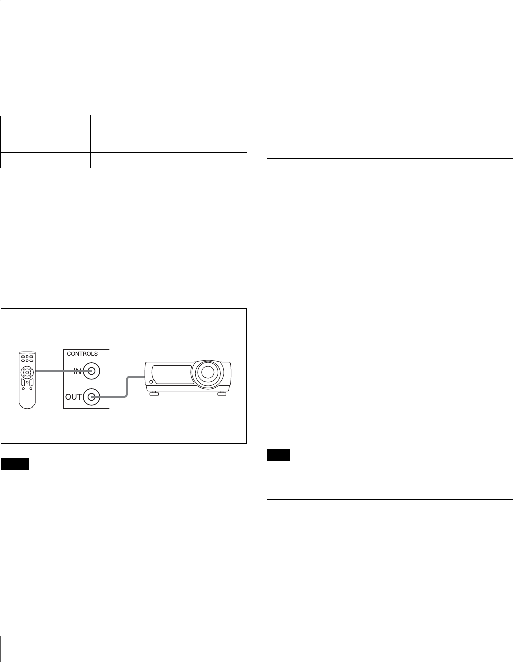
on the SRP-X500P. Also, when a wired remote
commander supplied with a projector is connected to the
CONTROL S IN connector on the SRP-X500P, the
projector settings can be performed on the SRP-X500P.
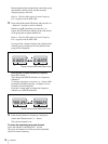
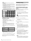
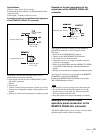
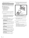
Connect the projector and the projector’s remote
commander to the SRP-X500P as shown below.
Notes
• To supply power to the remote commander from the
SRP-X500P, use a stereo mini-plug cord to connect the
remote commander to the SRP-X500P. When batteries
are used to operate the remote commander, use a mini-
plug cord to connect the remote commander to the SRP-
X500P.
• When the projector’s wired remote commander is
connected to the PROJECTOR CONTROL CONTROL
S IN connector as illustrated above, the remote sensor on
the projector does not function and all commands from
the remote commander are transmitted through the
PROJECTOR CONTROL CONTROL S IN/OUT
connectors. Note that control of the projector by the
SRP-X500P takes priority over control by the remote
commander.
• The following restrictions apply when a projector is
controlled by the SRP-X500P via the PROJECTOR
CONTROL CONTROL S IN/OUT connectors.
− Video signals input from the INPUT VIDEO A/B/C
connectors are output to the OUTPUT VIDEO
connector in composite format only.
− Video signals input from the COMPONENT/RGB D/
E connectors are output to the OUTPUT
COMPONENT/RGB connector in either RGB or
component format. Be sure to change the input signal
format setting on the projector to match the format of
the signal output from the SRP-X500P.
− When “OTHER TERMINAL” is selected using the
SRP-X500P Manager software, the signal is
automatically input to the INPUT B connector on the
projector or the monitor.
REMOTE RS-232C connector
A PC installed with the SRP-X500P Manager software can
be connected to the REMOTE RS-232C connector to make
SRP-X500P settings from the PC. This connector can also
be used to connect an external system controller to allow
control of the SRP-X500P.
The specifications and the communication format for this
connector are as follows:
Specifications
Connector type: D-sub 9-pin, male, inch screw type
Electric specifications: Conforms to RS-232C
standards
Recommended cable: Multi-core shielded cable for
data communications
Cable length: 15 meters (50 feet) or less
Communication format
Baud rate: 38400 bps
Bit length: 8 bits
Stop bit: 1 bit
Parity: odd
Note
Use an RS-232C cross cable to connect the SRP-X500P
with a PC.
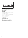
REMOTE PARALLEL connector
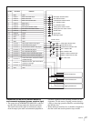
By connecting a simple circuit such as a switch or volume
controller to the REMOTE PARALLEL connector, the
SRP-X500P can be controlled remotely.
The specifications for this connector are as follows:
Product model PROJECTOR
PROTOCOL
SELECTOR setting
RGB input
connector on
the projector
VPL-PX15 A INPUT A
Remote
commander
Projector


