


6
ADCC1100
Chapter 2: Connection and Setup of the ADCC1100
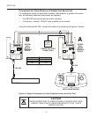
This chapter describes the power and data connections between the ADCC1100
keyboard and the switching system being used.
Supplied Equipment
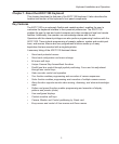
The ADCC1100 is supplied with the following equipment and accessories:
Two seven foot, MP-CBL connection cables
One MP-KMI wall-mount keyboard matrix interface
UK cable and plug, USA cable and plug, mainland European cable and plug
MP-PSU power supply unit
One Administrator's Smart Card
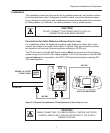
The power supply is connected to the jack connector of the MP-KMI network access
point. The power supply must be a UL listed, Class 2 type.
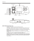
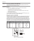
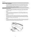
Setting the Jumpers for the MP-KMI
The MP-KMI contains six jumper links that must be configured according to figure 2.1.
Access to the jumpers is obtained by removing the screw holding the cover in place.
The table shows the connectivity of the links in the MP-KMI. For most purposes the
links should be left in the 2 and 3 position and this is the default factory setting. The
KMI performs a RX / TX cross over between the keyboard and matrix RJ45 connectors
in this mode. To remove the cross over (which may be required in certain situations),
change links 3 and 4 from the default 2 and 3 linked position, to the 1 and 2 position.
1
2
3
LK1
1
2
3
LK2
LK3
LK4
LK5
LK6
Rx
Tx
GND
Figure 2.1: MP-KMI Jumper Settings
Link Matrix RJ45 pin 1 and 2 Linked 2 and 3 Linked
Lk1 2 +12v Gnd
Lk2 3 Kbd Pin 3 n/c
Lk3 4 Kbd Pin 4 Kbd Pin 5
Lk4 5 Kbd Pin 5 Kbd Pin 4
Lk5 6 Kbd Pin 6 n/c
Lk6 8 +12 v Gnd.