


CHAPTER
1-1
Cisco RPS 675 Redundant Power System Hardware Installation Guide
78-15201-04
1
Product Overview
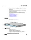
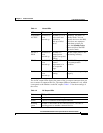
The Cisco RPS 675 Redundant Power System (RPS), model
PWR675-AC-RPS-N1=, provides N+1 redundancy. The RPS 675 provides
seamless failover to internal power supply failures for one of up to six switches.
The RPS 675 automatically senses when a connected device has experienced an
internal power supply failure. It then begins to supply power to the device. The
RPS supplies power until the power supply of the failed device is replaced or the
device is replaced. You can then return the RPS to active mode so that it is
available to supply power to another device.
Note The RPS 675 does not support an automatic switchover to the internal power
supply. You must press the Standby/Active button on the RPS so that the switch
again uses the internal power supply.
If a connected device fails, the RPS 675 sends status information to the other
connected devices and to network management software. This status information
alerts administration that these devices are not supported until the failed device or
the power supply of the failed device is brought up or replaced. To achieve
one-to-one redundancy, you must connect each device to a different RPS 675.
Note The RPS 675 is designed to provide backup for internal power supply failures of
connected device power supplies. It is not designed to act as a backup power
source that protects against losses of power due to external power outages.
We
recommend using an uninterruptable power system (UPS) as protection
against power outages.