


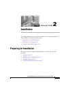

Chapter 2 Installation
Installing the Switch
2-8
Cisco RPS 675 Redundant Power System Hardware Installation Guide
78-15201-04
• One 16-pin-to-14-pin DC connector cable
• Mounting kit that contains:
–
Four rubber feet for mounting the switch on a table
–
Two mounting brackets
–
Four Phillips flat-head screws for attaching the brackets to the switch
–
Four Phillips truss-head screws for attaching the brackets to the switch
–
Four Phillips machine screws for attaching the brackets to a rack
Installing the Switch
This section describes these installation procedures:
• Table or Shelf-Mounting, page 2-8
• Rack-Mounting, page 2-9
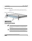
Table or Shelf-Mounting
Warning
Do not stack the chassis on any other equipment. If the chassis falls, it can
cause severe bodily injury and equipment damage.
Statement 48
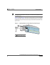
Follow these steps to install your chassis on a table or shelf:
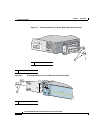
Step 1 Unpack the RPS 675.
Step 2 Attach the rubber feet from the accessory kit into the round recesses that are
located on the bottom of the chassis.
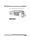
Step 3 Place the RPS 675 chassis on an appropriate table, shelf, or desktop.
Note If you have questions or need assistance, see the “Obtaining Documentation and
Submitting a Service Request” section on page xxiv.