


Chapter 2 Installation
Installing the Switch
2-10
Cisco RPS 675 Redundant Power System Hardware Installation Guide
78-15201-04
• When equipment installed in a rack (particularly in an enclosed rack) fails,
try this test: Operate the equipment by itself, if possible. Power off other
equipment in the rack and in adjacent racks to allow the unit under test a
maximum of cooling air and clean power.
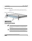
• Install the RPS 675 and the external devices to which it will connect in
adjacent shelves in a rack.
Tools and Equipment Required
To rack-mount the RPS 675, you need these tools and equipment:
• Number 12 Phillips screwdriver
• Number 8 Phillips screwdriver
• Screws for attaching the brackets to the RPS and the RPS to the rack
• Rack-mount brackets (19-inch or 24-inch) from the accessory kit
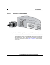
Attaching the Brackets to the RPS
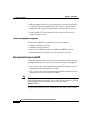
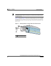
The bracket orientation and the screws that you use depend on whether you are
attaching the brackets for a 19-inch or a 24-inch rack. Use two of the supplied
screws to attach each bracket, according to the following guidelines:
• For a 19-inch rack, use the supplied number-8 Phillips flat-head screws to
attach the long side of the bracket to the RPS.
• For a 24-inch rack, use the supplied number-8 Phillips truss-head screws to
attach the short side of the bracket to the RPS.
Note If you install the switch in a 24-inch rack, an optional bracket kit that is not
included with the switch is required. You can order a kit that contains the 24-inch
rack-mounting brackets and hardware from Cisco (part number
RCKMNT-1RU=).
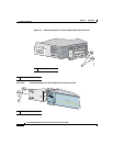
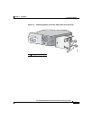
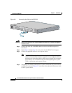
You can install the RPS into a rack with either the front panel or the rear panel
facing
forward.