


Chapter 1 Product Overview
Rear-Panel Description
1-8
Cisco RPS 675 Redundant Power System Hardware Installation Guide
78-15201-04
Rear-Panel Description
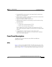
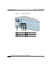
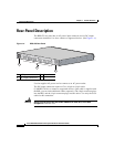
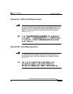
The RPS 675 rear panel has an AC power input connector and six DC output
connectors (numbered 1 to 6) to connect to supported devices. (See
Figure 1-4).
Figure 1-4 RPS 675 Rear Panel
Use the supplied AC power cord to connect to an AC power outlet.
The DC output connectors require a Cisco 16-pin-to-14-pin cable
(CAB-RPS-1614=) to connect to supported devices. (One cable is supplied with
the RPS; you can order additional cables separately.) The 16-pin connector plugs
into the RPS, and the 14-pin connector plugs into the device. Use only the Cisco
cable for this connection.
Warning
Attach only the Cisco RPS 675 (model PWR675-AC-RPS-N1=) to the RPS
receptacle.
Statement 100C
1 AC input connector 3 Fan exhaust
2 DC output connectors
10
0-2
40
V
~
1
0-6
A
5
0/60
H
z
D
C
O
U
T
P
U
T 1
D
C
O
U
T
P
U
T
2
D
C
O
U
T
P
U
T
3
D
C
O
U
T
P
U
T
4
D
C
O
U
T
P
U
T
5
D
C
O
U
T
P
U
T 6
1
2
V
/1
2
A
, -4
8
/ 7
.8
A
M
A
X
O
U
T
P
U
T
86664
2
1
3
C
A
U
T
I
O
N
:
R
P
S
N
O
T
H
O
T
P
L
U
G
G
A
B
L
E