


1-3
Cisco RPS 675 Redundant Power System Hardware Installation Guide
78-15201-04
Chapter 1 Product Overview
Front-Panel Description
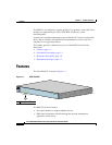
• Front-panel LEDs to show status for each output channel, internal power
supplies, fans, and temperature
• Quick switchover capability to ensure that the switch does not reboot if the
internal switch power supply should fail
• Support for telephone-enabled 24-port devices
• Small form-factor suitable for rack-mounting to provide maximum wiring
closet port density
• Two output levels:
–
–48 VDC with a maximum output of 375 W
–
12 VDC with a maximum output of 300 W
The two output levels provide a maximum total output power of 675 W.
The
–48 VDC mode powers telephone systems in Power over Ethernet (PoE)
switches.
• A single 48-inch (1.2-meter) 16-pin-to-14-pin connector cable
(CAB-RPS-1614=) to allow connection to an external device. Additional
cables can be ordered separately.
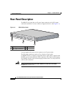
Front-Panel Description
The RPS 675 front panel includes the status LEDs for the RPS and a
Standby/Active button.
LEDs
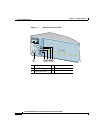
Figure 1-2 shows the Cisco RPS 675 LEDs. The LEDs display the status of the
RPS and show whether the RPS is powering a connected device. LEDs can be off,
green, or amber.
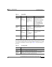
Table 1-1 lists the status LEDs and the meanings of the colors.