


1-9
Cisco RPS 675 Redundant Power System Hardware Installation Guide
78-15201-04
Chapter 1 Product Overview
Deployment Strategies
Deployment Strategies
You can deploy the Cisco RPS 675 in a variety of situations with mission-critical
applications.
One application might be in a voice and data network in which switches (such as
a Catalyst 3550-24PWR or a Catalyst 3750-48PS switch) are connected to Cisco
IP
phones and PCs. Connecting an RPS 675 to the switches can prevent voice
network failures that are caused by switch failures.
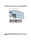
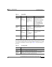
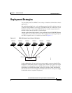
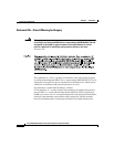
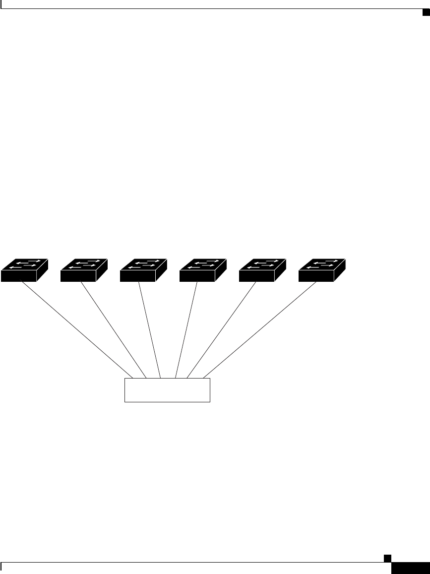
Another application might be that of using traditional data 10/100/1000 Ethernet
switches that carry mission-critical data. These applications would typically use
one RPS to support one to six switches as shown in
Figure 1-5.
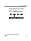
Figure 1-5 RPS 675 Supporting a Group of Switches
In this configuration, if one device has a power-supply or power-related failure,
the RPS 675 immediately begins to supply power to this device and is no longer
available as a backup power source for the other devices. The RPS sends status
information to network management software to alert the system administrator
that the other devices are not supported until the failed device or the power supply
in the failed device is repaired or replaced.
Network
switch
Network
switch
Network
switch
Network
switch
Network
switch
Network
switch
RPS 675
DC out 1 DC out 6
86667