


Chapter 1 Product Overview
Front-Panel Description
1-6
Cisco RPS 675 Redundant Power System Hardware Installation Guide
78-15201-04
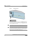
Standby/Active Button
The RPS 675 has a front panel Standby/Active button.
Note The RPS is in active mode (Standby/Active LED green) when it powers up.
It must be in standby mode every time you connect devices to it.
If you connect a device to the RPS when it is in active mode (Standby/Active LED
green), the RPS might unnecessarily begin supplying backup power to the device.
This situation might occur if you connect the device before it is powered up, or if
the RPS does not immediately sense that the device power supply was supplying
power. In this case, the RPS would not be available as a backup power source for
other connected devices.
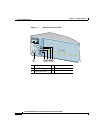
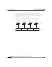
Figure 1-3 shows the Standby/Active button. Press the Standby/Active button to
change the RPS 675 from active mode to standby mode when you connect devices.
When you change the mode to active, the Standby/Active LED turns green.
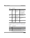
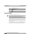
Blinking
amber
The RPS is providing power to the connected device; the output
is active.
Amber The RPS is in standby mode or in a fault condition.
Table 1-2 DC Output LEDs (continued)
Color DC Output Status