


Appendix B Connector and Cable Specifications
B-2
Cisco RPS 675 Redundant Power System Hardware Installation Guide
78-15201-04
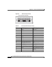
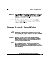
Figure B-2 16-Pin Connector Pinouts
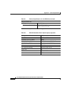
Table B-1 14-Pin and 16-Pin Connector Pinout
Pin Number 14-Pin Designation 16-Pin Designation
1 GND GND–48 V
2 –48 V –48 V
3 12 V 12 V
4 12 V 12 V
5 12 V 12 V
6 12 V 12 V
7 GND GND–12
8 GND GND–12
9 –48 V GND–48 V
10 RPS_PRES (RPS present) –48 V
11 RPS_CTRL 0 RPS_PRES (RPS present)
12 RPS_CTRL 1 RPS_CTRL 0
13 PWR_GOOD (power is good) RPS_CTRL 1
14 GND PWR_GOOD (power is good)
15 GND–12
16 GND–12 V
9 101112131415
1234567
16
8
Top of Connector (Logo Side)
86671