


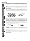
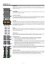
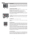

29. DISPLAY
The display always indicates the actual selected program number of the corresponding FX unit. The
display screen is covered with a protective foil to prevent it from being damaged during shipment.
Please remove the foil.
30. UP/DOWN
The UP/DOWN buttons are for selecting effect presets. Pressing and holding one of these lets you
scroll through the program numbers.
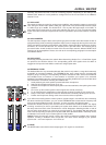
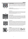
31/32. FX1/2 to AUX3/4
These controls allow adding the output signal of FX1 or FX2 to the monitoring channel. Experience
has revealed that the effect level in the monitor mix has to be lower than the level in the main mix,
since the distance between monitor speakers and artists is much shorter.
33. FX ON
This switch switches an internal FX unit on and the green LED lights. Please keep in mind that you
can also use an external footswitch for switching the FX unit ON. In this case, the LED also shows
the actual operational status of the FX unit. If you want to use a footswitch, the FX ON switch has to
be engaged fi rst. The corresponding FX unit is activated and you can use the footswitch to switch the
selected effect program on or off.
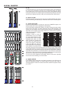
34. PFL
Engaging the PFL button routes the audio signal to the headphones bus, so that it is present at the
phones output connector. The phones output volume is independent of the corresponding FX fader’s
setting (PRE FADER LISTEN).
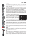
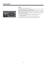
35. PEAK LED
These indicators signal if the internal FX units or the AUX 1/2 SEND signals are on the verge of
clipping. To achieve an adequate S/N ratio, please adjust the FX units’ input level as follows:
Setting Instructions:
1. Establish a “dry” mix – without effect settings – according to the previous descriptions.
2. Position the effect return fader of the corresponding effect channel at the –5dB mark.
3. Use the UP/DOWN buttons to select the desired FX program preset.
4. Press the FX ON switch.
5. Play (start the reproduction of) the sound source connected to the desired input channel and
adjust the desired amount of the FX signal, using the AUX/FX controls of this input channel.
Repeat this step for all input channels that you want to include in your effect mix.
6. Monitor the Peak LED so that it only lights frequently at highly dynamic signal peaks. When
clipping occurs, reduce the AUX/FX controls in the channels.
7. Use the FX to AUX control to add the effect mix to the monitor mix.
In case you are using a different effect setting for the second FX unit, you have to repeat steps 2 - 7,
respectively. Pay some attention to the peak indicators when operating your CMS to be able to quickly
interact when the signal levels exceed the normal range and enter clipping.
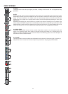
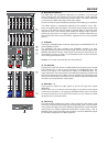
36. EFFECT RETURN
These stereo faders are used to determine the effect amount added to the main mix. In case you have
to set these faders at a position above the +5dB mark, the level of the FX unit’s input signal might be
too low. If that is the case, use the AUX/FX SEND controls to increase the input levels.
Use the FX faders to set the fi nal amount of the effects signal that is added to the main mix.
EFFECTS 1/2
14