


INPUT MONO
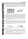
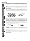
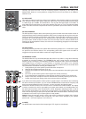
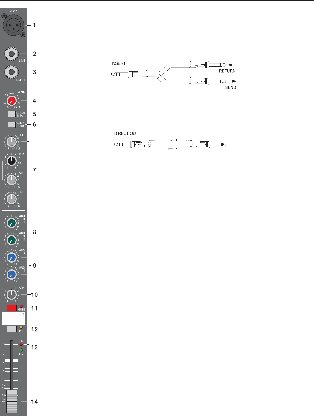
3. INSERT
Stereo phone jack with breaker function and with the low impedance output being assigned to the tip (send) and
the high impedance input (return) to the ring. This jack allows the connection of external FX units, compressors,
limiters, EQs, de-noisers, etc. into the corresponding channel’s signal path. The insertion point is post gain
controls, Lo-Cut fi lters, and voicing stage but pre sound shaping section and channel faders. You have to use a
stereo phone plug (Y-cord) – according to the following diagram.
When using the insert socket as a DIRECT OUT (Pre EQ), the stereo phone plug’s tip and ring have to be short
circuited, so that the audio signal is not interrupted. If you are using a monaural phone plug instead, you will
get a DIRECT OUT with breaker function – the audio signal can be output but the internal signal fl ow inside the
channel’s signal path is interrupted.
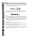
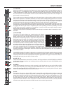
4. GAIN
Rotary control for adjusting a MIC/LINE input’s sensitivity. These controls let you optimally adjust the incoming
signals to the mixer’s internal operation level. Cautious adjusting offers the benefi ts of improved S/N-ratio and
provides you with the full bandwidth of the CMS’s outstanding sound capabilities. On the XLR-type connectors
an amplifi cation of 0dB is achieved when the control is set all the way at its counterclockwise rest and +60dB
when the control is set at its clockwise rest. Especially when dealing with very low input levels – during vocal
recordings or when the sound source is located in a distance – the high gain is extremely profi table. Using the
LINE-input, the signal is generally attenuated by –20 dB while maintaining the total adjustment range of 60dB.
The LINE-input’s unity gain – no amplifi cation (0 dB) – is achieved at the 20dB mark. The following is meant as
a short introduction to assist you in determining correct input levels:
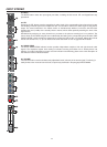
Setting Instructions:
1. Set the gain control and the corresponding channel fader to their minimum values.
2. Connect the desired sound source (microphone, musical instrument, etc.) to the desired MIC or LINE
input.
3. Start the reproduction of the sound source at the highest volume level to be expected – respectively sing or
speak as loud as possible directly (short distance) into the microphone.
4. While doing so, adjust the input level using the gain control, so that during the loudest passages the PEAK
LED is just not lit, but the SIGNAL present LED lights constantly.
This is the basic channel setting, leaving you with at least 6dB of headroom, i.e. you have at least a range of
6dB before signal clipping occurs. In case you intend to make further adjustments to the channel’s tone control
setting, you should perform steps 3. and 4. again afterwards, since changes in the sound shaping section also
have an infl uence on the channel’s overall level.
6