


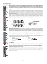
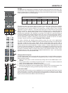
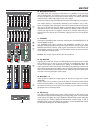
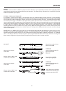
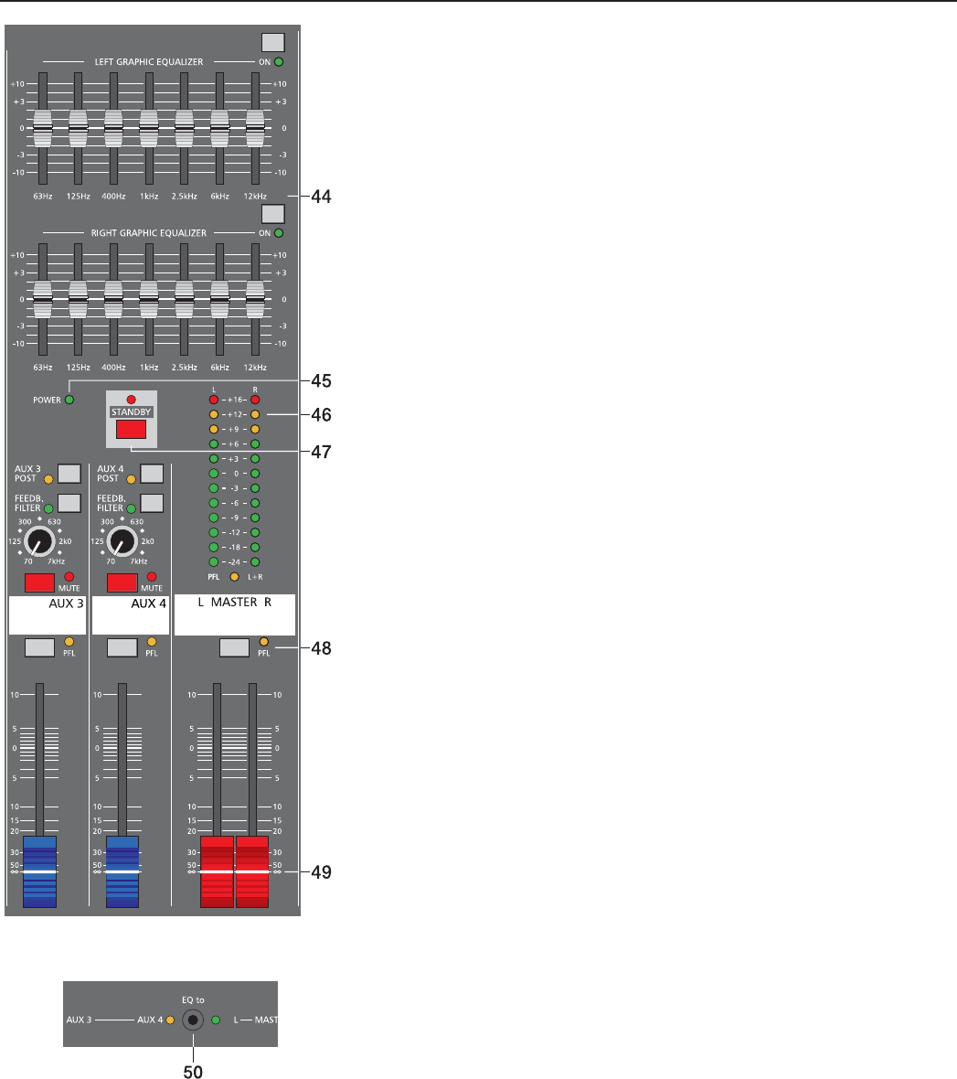
46. MASTER LED-DISPLAY
The CMS offers two 12-segment LED-chains for indication of left and right
channel output levels. The indication range of the LED-meter is 40dB, indicating
the levels (in dBu) that are present at the master outputs. The meter’s 0dB mark
is referenced to a 0dBu output signal at the mixer output.
Please mind that the signal indicated by the Master LED display is pre equalizer.
The master display is automatically switched to PFL-indication, once a PFL-
button is engaged (yellow LED lights). The left LED chain indicates the PFL-level
(the sum of all channels with PFL-buttons engaged) while the right LED chain
indicates the level of the summed master output. This display mode is useful for
checking the signal level of a single input channel, for example. When doing so,
please make sure that the only PFL-button engaged is the one of that specifi c
channel.
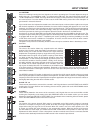
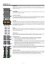
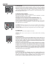
47. STANDBY
Pressing the STANDBY button mutes the output signals at the MASTER OUT L/R
and the MONO OUTPUT.
The STANDBY LED lights indicating that STANDBY operation has been
activated. All audio signals coming from the input channels are not output via the
MASTER OUTPUTS. However, audio signals connected via 2Track Return are
still outputted, providing you with a very comfortable solution to play intermission
music during performance breaks.
Caution: The monitor outputs AUX3/4 are still operational.
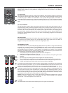
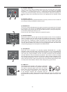
48. PFL MASTER
Engaging the master PFL-button, the PRE FADER stereo master signal is routed
to the phones bus, so that it can be monitored via headphones output. The
volume of this signal is not affected by the setting of the MASTER fader. The
meter instrument in the master section is simultaneously switched, so that the left
LED-chain indicates the level (in dBu) of the summed pre-fader L/R master signal
channel, which basically is the master bus level, while the right LED indicates the
level of the summed post-fader master output.
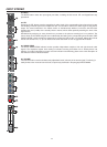
49. MASTER L + R
Level controls to adjust the output signals of the left and right main outputs
(MASTER).
Please, make sure to set the input channel faders or at least the master faders
to their minimum position, or to engage the STANDBY switch, before connecting
an external sound source to an input. This will save you, your audience, and the
equipment from unnecessary stress.
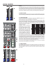
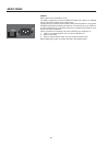
50. EQ Routing
This switch allows assigning the internal 7-band equalizer to the master or the
AUX3/4 buses wit two LEDs indicating the corresponding mode. In EQ to AUX3/4
mode (yellow LED lights) the “LEFT GRAPHIC EQUALIZER” controls the AUX3
channel while the “RIGHT GRAPHIC EQUALIZER” controls AUX4. In EQ to
MASTER mode (green LED lights) both equalizers control the MASTER outputs
as described in paragraph 44 “7-Band Equalizer”.
MASTER
17