


Generally, the AUX3/4 channel is used for monitoring purposes. Depending on the setting of the
AUX3/4 POST buttons, it is also possible to confi gure the bus for the connection of an additional,
external FX unit.
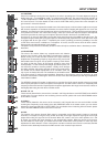
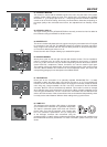
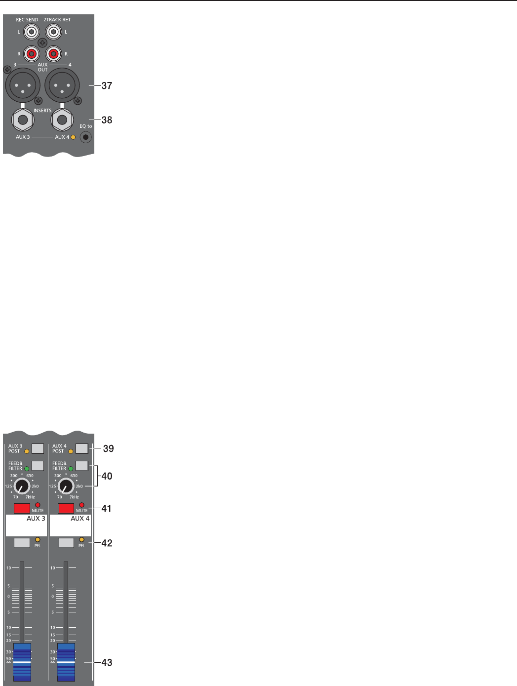
37. AUX3/4 OUT
This output provides connection for monitor power amplifi ers, active speaker systems or external FX
units. Using the AUX3/4 fader allows setting the output level of this electronically balanced output
in a wide range up to +20dBu. The AUX3/4 OUT – like any other XLR-type output on the CMS – is
relay-switched to prevent power-on noise when switching the mixer on or off. Use balanced cables
for the connection of external components whenever it is possible to prevent the induction of external
noise.
38. AUX3/4 INSERTS
The low impedance output of these stereo phone-type jacks for AUX3 and 4 with breaker function is
assigned to the tip (send) and the high impedance input (return) is assigned to the ring of the connector.
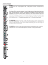
These jacks allow incorporating external third octave band or octave band EQs, compressors, limiters,
de-noisers, etc. into the AUX channel. The insertion point is pre AUX faders. The insertion point is
pre master faders. As well as with the inserts of the monaural input channels, different DIRECT OUT
functions can be accomplished. Please, also refer to the corresponding paragraph in the description
of the MONO INPUT.
39. AUX3/4 POST
As already previously described, this switch allows determining whether Pre- or Post-Fader signals
are present at the AUX3/4 channel. The corresponding yellow LED signals when the switch is
engaged and all input channel AUX3/4 controls are assigned post fader.
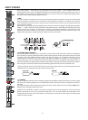
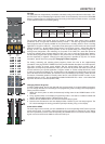
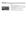
40. FEEDBACK FILTER
The feedback fi lter is a very narrow banded notch fi lter, which is only active in a range that is extremely
susceptible for acoustical feedback. The FEEDBACK fi lter rotary control sets the corresponding
frequency range. Pressing the corresponding ON button activates the fi lter. Several circumstances
and conditions have an infl uence on how sensitive or insensitive your system is for acoustical
feedback. The following notes are meant to assist you in avoiding feedback and you should take them
into consideration even before activating the feedback fi lter:
1. Avoid positioning the main speaker systems behind the microphones.
2. Switch off all microphones that are not in use.
3. Consider the microphones’ different polar patterns and characteristics, when placing the monitor
speakers.
4. Do not turn up the monitor system’s volume higher than actually necessary.
5. Try to avoid extensive equalization on channels that you want to include in your monitor mix.
6. Keep in mind, that a microphone “behaves” different when somebody stands right in front of it.
7. Position the microphones aiming at the sound source as direct as possible.
If you still have the feeling that the monitor system’s acoustic output is not suffi cient, after considering
the above mentioned precautions, you can use the FEEDBACK fi lter to attenuate the frequency that
tends to generate feedback the most. Therefore, you have to perform the following steps:
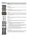
Increase the AUX3/4 (monitor) level until the limit is reached where feedback starts. The slightly
“hovering” sound that you hear is generated by the system itself. Switch on the feedback fi lter, turn
the rotary control and set it at the mark where the “sound” disappears. Switching the fi lter on and off
lets you easily check whether you tuned in the correct frequency. The feedback fi lter attenuates the
level of the corresponding frequency band by about 9dB. Since the fi ltered band is extremely narrow,
an alteration in the sound of your monitor system is hardly audible.
Caution: Please be extremely careful in driving the system just below the feedback limit. Careless
operation, resulting in feedback noise at high SPL, can cause severe damage to your speaker
systems and – even more important – the human ear.
41. MUTE
The MUTE button mutes the Aux-Send output signal. PFL signals are not affected.
AUX3&4 / MASTER
15