


Notice: Be sure to follow figures two and three when making your own
cables. Do not use the ground lug on the XLR connector. Do not connect
the cable’s shield conductor to the ground lug or allow the shield conductor
to come in contact with the XLR’s outer casing. Grounding the shield could
cause a short circuit and erratic behavior.
Power Supply: Before plugging your unit in, be sure the source voltage in
your area matches the required voltage for your Elation
® DMX Programmer.™
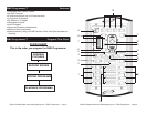
The Elation® DMX Programmer
™
is 120v only. Because line voltage may vary
from venue to venue, you should be sure your controller voltage matches the
wall outlet voltage before attempting to operate you fixture.
DMX-512: DMX is short for Digital Multiplex. This is a universal protocol used
as a form of communication between intelligent fixtures and controllers.
A
DMX controller sends DMX data instructions from the controller to the fix
-
ture. DMX data is sent as serial data that travels from fixture to fixture via the
DATA “IN” and DATA “OUT” XLR terminals located on all DMX fixtures (most
controllers only have a DATA “OUT” terminal).
DMX Linking: DMX is a language allowing all makes and models of different
manufactures to be linked together and operate from a single controller, as
long as all fixtures and the controller are DMX compliant.
To ensure proper
DMX data transmission, when using several DMX fixtures try to use the short
-
est cable path possible. The order in which fixtures are connected in a DMX
line does not influence the DMX addressing. For example; a fixture assigned a
DMX address of 1 may be placed anywhere in a DMX line, at the beginning, at
the end, or anywhere in the middle. When a fixture is assigned a DMX address
of 1, the DMX controller knows to send DATA assigned to address 1 to that
unit, no matter where it is located in the DMX chain.
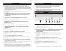
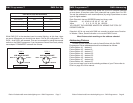
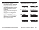
Assigning DMX Address: Each dipswitch has a preset value. A specific DMX
address is set by combining the dipswitches that sum your desired value.
For example: To achieve a DMX address of 7, combine dipswitches 1, 2, and
3. Since dipswitch 1 has a value of 1, dipswitch 2 has a value of 2, and dip
-
switch 3 has a value of 4, the combination of the three create a DMX value
of 7. (See example below).
Set DMX address 1: Set DMX address 7:
Dip-switches # 1 = 1 Dip-switches # 1 = 1
2 = 2
3 = 4
= 7
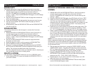
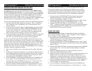
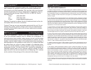
Data Cable (DMX Cable) Requirements (For DMX and Master/Slave Op
-
eration): Your DMX Programmer™ and your fixture require a standard 3-pin
XLR connector for data input and data output (Figure 1). If you are making
your own cables, be sure to use standard two conductor shielded cable (This
cable may be purprogramd at almost all pro sound and lighting stores). Your
cables should be made with a male and female XLR connector on either end
of the cable. Also remember that DMX cable must be daisy chained and can
not be split.
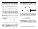
DMX512 IN
3-PIN XLR
SOUND
REMOTE
CONTROL
INPUT
POWER
INPUT OUTPUT
SOUND
REMOTE
CONTRO
L
INPU
T
POWER
INPUT OUTPUT
SOUND
REMOTE
CONTRO
L
INPU
T
POWER
INPUT OUTPUT
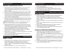
DMX512
DMX+,DMX-,COMMON
1
2
3
Termination reduces signal errors and
avoids signal transmission problems
and interference. It is always advisable
to connect a DMX terminal, (Resistance
120 Ohm 1/4 W) between PIN 2 (DMX-)
and PIN 3 (DMX +) of the last fixture.
1
2
3
1
2
3
DMX +
DMX -
COMMON
DMX512 OUT
3-PIN XLR
Figure 2
Figure 3
1 Ground
1 Ground
XLR Male Socket
XLR Pin Configuration
3 Hot
2 Cold
2 Cold
3 Hot
XLR Female Socket
Pin 3 = Data True (positive)
Pin 2 = Data Compliment (negative)
Pin 1 = Ground
Special Note: Line Termination.
When longer runs of cable are used, you
may need to use a terminator on the last unit to avoid erratic behavior. A ter-
minator is a 90-120 ohm 1/4 watt resistor which is connected between pins
2 and 3 of a male XLR connector (DATA + and DATA -). This unit is inserted
in the female XLR socket of the last unit in your daisy chain to terminate the
line. Using a cable terminator (ADJ part number Z-DMX/T) will decrease the
possibilities of erratic behavior.
DMX Programmer™ DMX Set UpDMX Programmer™ DMX Set Up
DMX512 IN
3-PIN XLR
SOUND
REMOTE
CONTROL
INPUT
POWER
INPUT OUTPUT
SOUND
REMOTE
CONTRO
L
INPU
T
POWER
INPUT OUTPUT
SOUND
REMOTE
CONTRO
L
INPU
T
POWER
INPUT OUTPUT
DMX512
DMX+,DMX-,COMMON
1
2
3
Termination reduces signal errors and
avoids signal transmission problems
and interference. It is always advisable
to connect a DMX terminal, (Resistance
120 Ohm 1/4 W) between PIN 2 (DMX-)
and PIN 3 (DMX +) of the last fixture.
1
2
3
1
2
3
DMX +
DMX -
COMMON
DMX512 OUT
3-PIN XLR
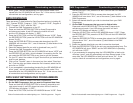
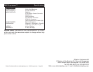
Figure 4
5-Pin XLR DMX Connectors.
Some manufactures use 5-pin XLR connectors
for DATA transmission in place of 3-pin. 5-pin XLR fixtures may be implement-
ed in a 3-pin XLR DMX line. When inserting standard 5-pin XLR connectors
in to a 3-pin line a cable adaptor must be used, these adaptors are readily
available at most electric stores. The chart below details a proper cable con-
version.
Elation Professional® www.elationlighting.com - DMX Programmer Page 6Elation Professional® www.elationlighting.com - DMX Programmer Page 5