


2
The structure of a program
Synthesizer
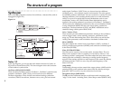
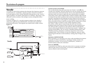
Each of the R3’s programs consists of two timbres, a master effect, and an
arpeggiator (Figure 0-1).
Figure 0-1
Timbre 1
Timbre 2
Synth
Synth
EQ
EQ Insert FX 1/2
Insert FX 1/2
Arpeggiator
Master FX
Audio Input 2
Audio Input 1
OUTPUT
(L/MONO, R)
AUDIO INPUT 1, 2
OSC1
MIXER
FILTER1
FILTER2
DRIVE/WS
MOD SEQUENCER
AMP
OSC2
NOISE
EG1
KBD TRACK
PAN
KBD Track
Velocity
Pitch Bend
Mod Wheel
Filter Routing= Individual
Drive/WS Position
= PreAmp
To EQ
Free Assign
Free Assign
OSC MOD
Synth
EG1
EG2 EG3
LFO1 LFO2 MIDI 1–3
VIRTUAL PATCH
Timbre 1/2
In the top diagram, you can see that each timbre consists of a Synth, an
EQ, and two Insert Effects (IFX). The lower diagram shows the structure
of each timbre’s synth section.
Oscillator (OSC1/OSC2/NOISE)
There are three Oscillator sources; Oscillator 1, Oscillator 2, and the noise
generator. Oscillator 1 (OSC1) lets you choose from seven different
oscillator algorithms. These include conventional analog synthesizer
waveforms, DWGS waveforms, formant waves, noise, plus an external
audio signal. Oscillator 2 (OSC2) lets you choose from four different
oscillator waves - sine, triangle, square, and sawtooth. The noise genera-
tor (NOISE) produces white noise. You can use this for a variety of sound
shaping situations, such as adding breath noise for a wind instrument
sound, or as part of a special effect sound. Modulation such as cross-
modulation, unison, and VPM (Variable Phase Modulation) can be
applied to the analog synthesizer waveforms of Oscillator 1. Oscillator 2
can be used as the modulating oscillator for the sync modulation (SYNC)
or ring modulation (RING) that are such classic analog synthesizer
techniques. The best elements of SYNC and RING modulation can be
combined using a third option: RING SYNC.
Voice / Unison / Pitch
These sections provides additional parameters relating to the oscillators,
such as trigger mode, unison stacking, transpose, portamento, bend
range, etc. For die-hard analog fans, this is also where you can find the
Analog Tune parameter, used to introduce simulated oscillator drift.
Mixer (MIXER)
The mixer adjusts the volume levels of oscillator 1 (OSC1), oscillator 2
(OSC2), and the noise generator (NOISE), and sends the combined signal
to the filter (FILTER).
Filter (FILTER1/FILTER2)
The filter section consists of two multi-mode, resonant filters. The two
filters can be routed in series or parallel, or even side by side in a "one
oscillator per filter" arrangement. The filters adjust the tone of the sound
coming from the oscillators by boosting or cutting specific frequency
regions. Filter settings will have a major impact on the sound. By default,
envelope generator 1 (EG1) is set to vary the cutoff frequency of the
filters over time.
Amp (AMP)
Traditionally, the amp section controls the output volume (AMP) and the
panning (PAN), or the position in the stereo field. By default, envelope
generator 2 (EG2) is set to vary the volume level over time.
Drive/Wave Shape (DRIVE/WS)
The R3 provides additional features to add more tonal complexity and
“edge” to the sound - including Drive, Wave Shape control (DRIVE/WS).