


14
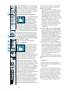
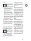
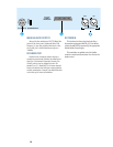
Mic In
The channel microphone input (1) is a stan-
dard 3-pin female mic connector (call me
Cannon or call me XLR, just don’t call me late
for dinner). Pin one is ground, pin two is signal
high (+), pin three is signal low (–), as per the
(finally) agreed-upon international standard.
NOTE: Don’t use these XLR’s for line level sig-
nals — see “Line In”.
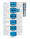
Line In
The channel Line Input (2) is a TRS (tip-
ring-sleeve) balanced 1/4" phone jack, with
ground wired to the sleeve, signal high (+) to
the tip and signal low (–) to the ring. Nominal
input level is +4dBu, with a wide range of levels
accommodated by adjustment of the TRIM con-
trol. These jacks also accommodate TS
(tip-sleeve) unbalanced 1/4" phone plugs. See
Appendix A: Connections for more information.
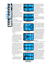
Direct Out
The channel Direct Out (3) is a nominal
+4dBu unbalanced TS 1/4" phone jack, con-
nected to the output of the channel line
amplifier post-EQ/post-fader/post-mute. The out-
put signal of each channel strip is always
available at the Direct Out jack. Using the Direct
Out does not interrupt the normal signal flow
through the channel.
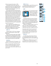
Channel Insert
The channel Insert jack (4) allows you to in-
sert external processing equipment (such as a
compressor, gate, you name it) into the main sig-
nal path of the input channel strip. The insert
point is after the FLIP switch (which also means
that it is after the MIC/LINE or TAPE IN pream-
plifiers) but before the LO CUT filter, EQ and
fader MUTE switch. The TRS jack is configured
for the Tip (send), Ring (return) and Sleeve
(signal ground). See Appendix A for more details
on using external processing and channel inserts.
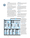
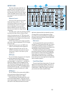
CHANNEL
16
MIC/LINE
LINE
IN
DIRECT
OUT
BAL-
UNBAL
INSERT
TIP = OUT
RING = IN
PHANTOM
POWER
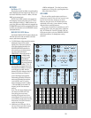
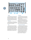
JACK PANELS (INPUT STRIP &
MASTER OUTPUT)
All of the inputs, outputs and insert points are
located on the jack panels on the top and the
rear panels of the mixer. An external patchbay is
not required, although it does make life easier.
Let’s start by listing what is NOT on the
FRONT jack panel:
• The console outputs to the multitrack tape
recorder (the Submaster/Tape outputs)
• The console inputs from the multitrack tape
recorder
• The balanced main L/R (XLR connector)
outputs (on the rear panel)
All other connections are made at the top of
the front panel, either above the channel Input
Strips or above the Output Panel.
INPUT STRIP
Each channel input strip has its inputs and
outputs located directly above the strip. The
connections are detailed next.
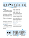
PHANTOM POWER
Microphone phantom power (+48 VDC) is ap-
plied to the channel strips in groups of eight. The
phantom on/off switch for channels 1-8 is located
above channel 8; the switch for 9-16 above chan-
nel 16, and so on. It has a “ramping” function,
which means it gradually ramps from 0 to 48V
when you turn it on, and ramps back down when
you turn it off. This helps
protect your microphones.
We suggest that before
plugging or unplugging mics,
you turn off the PHANTOM
power. Give it about a minute
to settle while you get a Diet YooHoo or call your
stockbroker. Then connect or disconnect the
microphone(s) and turn PHANTOM power back on.
CAUTION: After switching PHANTOM Power
on or off, wait 1 minute before changing any mic/
line switch settings in that eight-channel block.
Another safe alternative is to turn both TRIM
and Channel Faders down for that bank of eight
channels before switching.
Let there be light (sockets)
Additionally, one or two BNC connectors (de-
pending upon the number of input channels on
the console) are provided above the input strips
for gooseneck lamps. The BNCs are wired with
the center post at +12 VDC. Mackie doesn’t offer
lamps, but most dealers do. We recommend
LittleLite lamps #12G or #12G-HI (a high-inten-
sity version).