


23
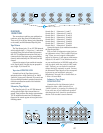
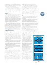
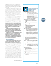
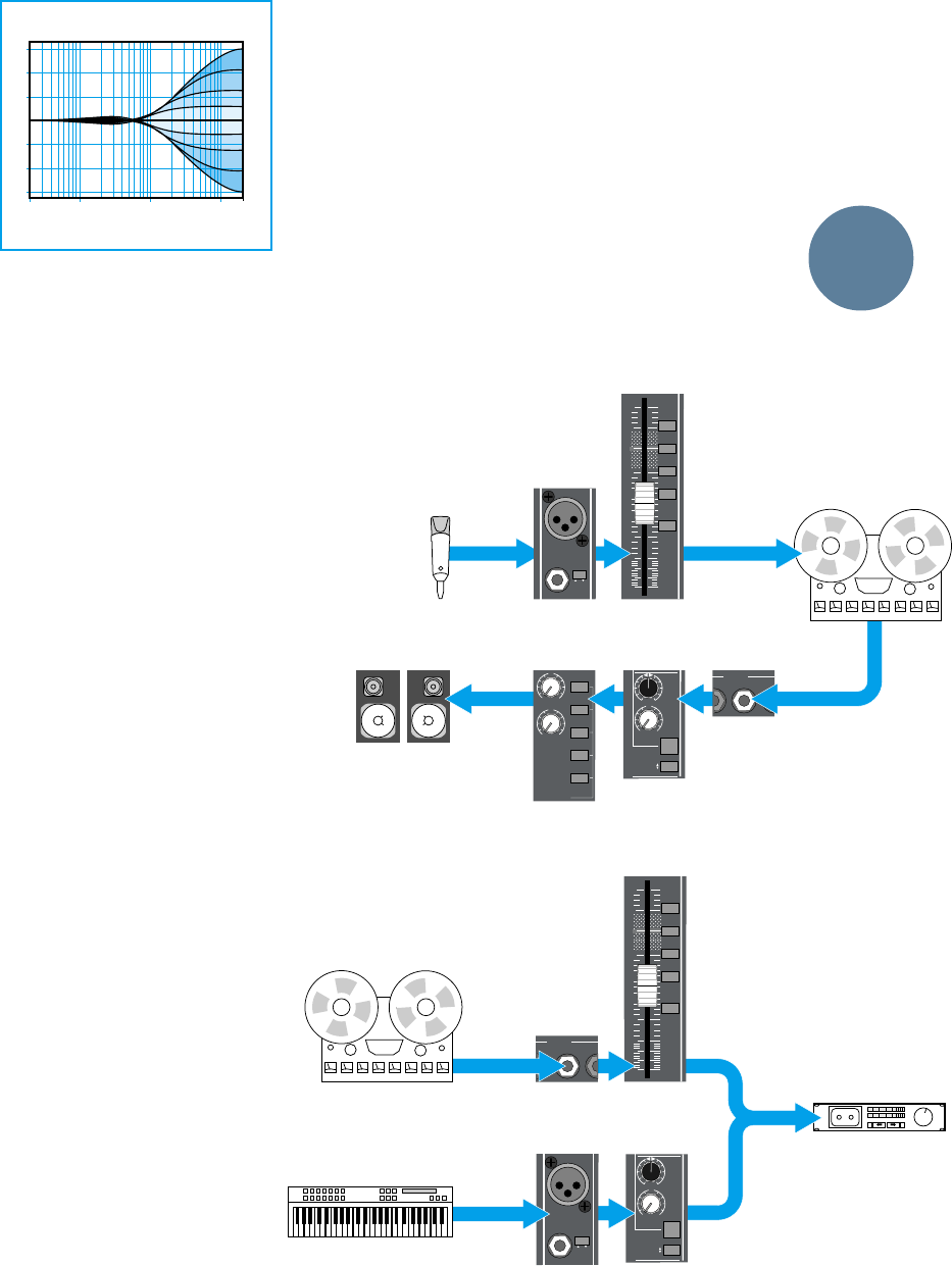
The LO and HI sections of the EQ are shelv-
ing equalizers, with a family of curves shown in
Figure 3. As you can see, shelving EQs lift or
lower the entire range of frequencies above or
below a certain point. Most tone controls on
stereos are shelving EQs, often set at 100Hz for
the bass and 10kHz for the treble. The LO EQ on
the 8•Bus is at 80Hz and the HI is at 12kHz.
The EQ IN/OUT SWITCH will completely re-
move the EQ circuit from the channels signal
path when disengaged, and activate the EQ
when engaged.
When the EQ section is split between the
channel strip and Mix B, the EQ IN/OUT switch
will only shut off the HI MID and LO MID bands.
The LOW CUT filter (also known as a high-
pass filter) reduces everything below about
100Hz. 75Hz is -3dB, and the lower the
frequency, the greater the attenuation. The slope
of the filter is 18dB/octave.
Connectors
If you’ve used a Mackie CR-1604 or
MicroSeries 1202, you’re familiar with the vari-
ous kinds of connectors used with a mixing
board. If you’re new to this whole thing, review
the drawings in Figure 4 on Page 22. They’re also
described in detail in Appendix A on page
48 of this manual.
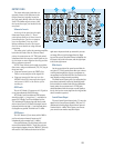
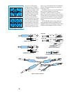
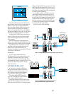
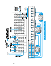
A BIT MORE ON MIX-B/FLIP
In Section 2, we described FLIP’s use
during tracking and mixdown. Before you
actually get involved with recording, we’d
like to spring a couple of block diagrams
on you that may clarify things further.
The switch labeled FLIP selects the
input that is actually fed into the channel
fader (and the MIX-B control).
As the label indicates, the MIC/LINE input
(after Mic/Line preamp) is fed to the channel
fader when the FLIP switch is in the up position
(Figure 5). When FLIP is up, the channel is fed
MIC/LINE and MIX-B gets TAPE. That way, you
can use MIX-B to monitor the signal as it comes
back from the recorder. This is the normal mode
for tracking and overdubbing.
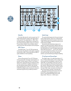
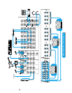
In the down position, the TAPE return (the
output signal from the corresponding track of
your recorder) is fed to the channel fader (Fig-
ure 6). When FLIP is down, the channel input is
TAPE and MIX-B receives MIC/LINE. That en-
ables you to use each channel’s MIC/LINE input
for another input during mix down. Thus down
is the normal position for mixing.
For PA, leave the FLIP switch up.
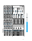
dB
30
20
5
10
5-6
3-4
1-2
7- 8
L/R
MIX
OO
5
10
40
50
60
U
TAPE IN
24
Channel
Tape Input
Channel
Fader
Channel
Input
+15
OO
U
MIX-B
SOURCE
OUTPUT
INPUT
PAN
LEVEL
SHIFT
HI/LO EQ
MONITOR
LR
Channel
Mix B/Monitor
Mixdown DeckMulti-track Deck
(PLAYBACK)
Additional mic or line input
24
CHANNEL
LINE IN
MIC/LINE
Figure 5: FLIP/MIX-B signal path during tracking (“flip” switch up)
Figure 6: FLIP/MIX-B signal path during mixdown
showing additional input (“flip” switch down)
Channel
Input
Channel
Fader
Channel
Tape Input
Channel
Mix B/Monitor
Speaker
Section
MONO
TAPE
MIX-B
L/R MIX
EXTERNAL
SOURCE
SPEAKERS
CNTRL RM
STUDIO
+15
OO
U
+15
OO
U
+15
OO
U
MIX-B
SOURCE
OUTPUT
INPUT
PAN
LEVEL
SHIFT
HI/LO EQ
MONITOR
LR
TAPE IN
24
dB
30
20
5
10
5-6
3-4
1-2
7- 8
L/R
MIX
OO
5
10
40
50
60
U
Multi-track Deck
(RECORD)
Control Room
Monitors
Mic
or
line
input
24
CHANNEL
LINE IN
MIC/LINE
1 LO & HI VARIABLE
(HI shown)
Only LO/HI Variable: Boost/Cut
Fig. 3
GENERAL
INFO