


4
+15
OO
U
MIX-B
LOW CUT
75 Hz
18dB/oct
SOURCE
FLIP SW
CHANNEL
PAN
LEVEL
SPLIT EQ
HI/LO EQ
TO MIX-B
MONITOR
LR
PA N
dB
30
20
10
5-6
3-4
1-2
7-8
L/R
MIX
-20
OL
OO
16
10
40
50
60
MUTE
5
5
SOLO
U
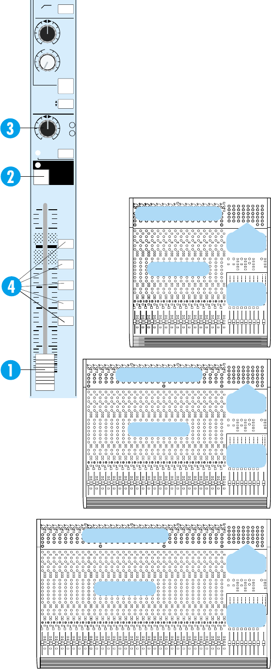
SECTION 2: Panel Layout and Function
INPUT CHANNELS (CHANNEL STRIPS)
The 16, 24 or 32 input channel strips on the
Mackie 8•Bus consoles are identical, and contain all
of the level, assignment and equalization controls for
each input channel. This section describes the con-
trols and functions of each feature of an input
channel in detail.
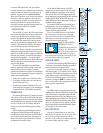
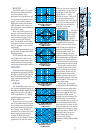
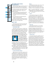
FADER
The channel fader (1) is 100 millimeters long,
with a precise logarithmic taper and attenuation in
dBs printed along the slot for exact and repeatable
level adjustments. The fader affects either the mic or
line input to the channel (for recording) or the tape
return to the channel (for mixing), depending on
the position of the FLIP switch.
MUTE
The MUTE switch, located at the top of the
fader (2), turns off the primary outputs of the
channel: the eight buses, the L & R buses, the
channel solo, the direct output and the post-
fader AUX sends. Pre-fader aux sends are not
muted. With the exception of lighting the mute
LED, pushing the MUTE switch is the same as
pulling the fader all the way down.
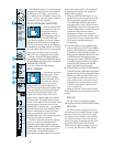
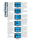
GOURMET PAN CONTROL AND
ASSIGNMENT SWITCHES
The PAN control (3), immediately above the
fader, pans the channel signal between the two sides
of the L/R Mix buses, and also between odd and even
pairs of buses 1 through 8.
The actual bus assignment of the PAN control
depends on the positions of the five assignment
switches located along the length of the fader.
With no switches depressed, the PAN control has
no effect (well, unless you solo the channel; it
still pans the solo).
Pushing the L/R MIX switch (4) assigns the PAN
to the main L/R Mix buses. Panning from L to R
moves the sound smoothly (with constant loudness)
from the left channel to the right channel. Assigning
the PAN to a pair of the 8 buses has a similar effect.
For example, pushing the 1-2 switch assigns the PAN
to buses 1 and 2, and panning L to R will move the
sound from bus 1 to bus 2 (from odd to even).
If you want to equally assign a channel to both
buses 1 and 2, leave the PAN control at the top, or
center, of its travel. If you only want bus 2, turn the
PAN control fully clockwise (to the right).
Other comparably-priced consoles provide as
little as 50dB attenuation/separation. We use active,
buffered circuitry and a custom-taper potentiometer
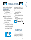
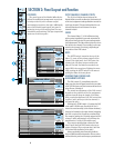
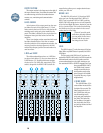
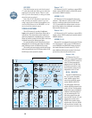
OVERVIEW
The panel layout of the Mackie 8•Bus Series
follows the traditional arrangement: input chan-
nel strips to the left, with a master output/
monitoring/cue section to the right. Additionally,
most of the Mackie input/output jack panel is
located at the top of the mixing panel, for easy
accessibility and patching. The tape outputs and
inputs are on the rear panel.
CHANNEL INPUT/OUTPUT
CHANNEL INPUT/OUTPUT
CHANNEL INPUT/OUTPUT
CHANNEL STRIPS
CHANNEL STRIPS
CHANNEL STRIPS
MASTER
SECTION
MASTER
SECTION
MASTER
SECTION
MASTER
I/O
MASTER
I/O
MASTER
I/O