


5
+15
OO
U
12k
MIX-B
EQ
LOW CUT
EQ IN
LO
MID
HI
HI
MID
FREQ
75 Hz
18dB/oct
SOURCE
FLIP SW
CHANNEL
45 3k
PAN
LEVEL
BAND
WIDTH
OCTAVES
500 18k
3k
FREQ
–15 +15
80
U
LO
SPLIT EQ
HI/LO EQ
TO MIX-B
MONITOR
LR
–15 +15
U
–15 +15
U
–15 +15
U
1k 5 k
250
220 350
3
2
1
12
NORMAL
PA N
-20
OL
SOLO
to achieve 87dB attenuation. You get far better
channel separation plus freedom from level shifts
caused by channel assignment and panning. In
addition, our pan pots are constant loudness.
When you sit between a pair of monitors and pan
from side to side, the apparent volume at your
ears should stay the same, no matter where the
signal is positioned. Our special pan circuitry
maintains consistent apparent energy whether the
pot is dead center, hard left or hard right.
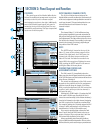
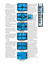
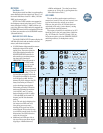
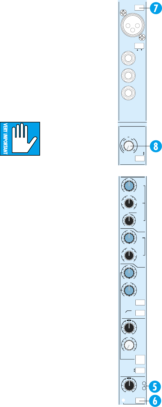
–20 AND OL LEDs
The two LEDs (5) next to the PAN control check
the channel strip signal level at three important cir-
cuit points: at the output of the mic/line preamp,
after the EQ and after the channel fader amplifier.
The green LED marked –20 is there to assure
you that, yes, something is plugged into the channel
(and yes, it does have some output). Most signals
more interesting than tape noise will cause the
green LEDs to flicker, so they give you a good visual
indication of which channels are active. Any peaks
higher than –20dBu (@ 1kHz) trigger the indicator.
When we say “channel”, we mean the signal going
through the channel fader… but not the signal
going through the MIX B Section. Please refer to the
MIX B section of this manual, starting on the next
page, for more details.
The red LED, labeled OL for overload, lights
when the signal level is high enough to cause clip-
ping at any of the three test points. In normal
operation it will almost never light. If it is flashing at
you, your level in that channel is much too high. You
need to turn something down.
• First try the mic/line trim. If that has no effect,
• Turn down the EQ and/or the insert device,
and if that doesn’t fix it,
• Turn down the channel. If this doesn’t fix it, your
input signal is too hot (gasp). Use an external pad
to reduce the level (see the sidebar on page 25).
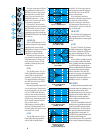
CHANNEL SOLO
The channel SOLO switch (6) assigns the output
of the channel PAN control to the stereo solo buses
and disconnects all other sources from the monitor
section. SOLO does not interrupt the eight Submas-
ters, the L/R Mix or the AUX sends, and can be
used at any time without affecting the recording
process.
SOLO is handy for spot-checking the presence
and quality of individual inputs while setting up,
recording and mixing. More than one SOLO switch
may be pressed at the same time, allowing you to
listen to the blend of any combination of channels
throughout the console in stereo.
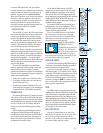
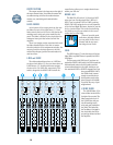
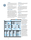
TRIM
FLIP
TAPE
MIC/LINE
CHANNEL
16
GAIN
+4
–10
dBV
50
dB
10
dB
L
I
N
E
S
E
N
S
I
T
I
V
I
T
Y
M
I
C
G
A
I
N
-40
dBV
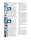
CHANNEL
16
MIC/LINE
LINE
IN
DIRECT
OUT
BAL-
UNBAL
INSERT
TIP = OUT
RING = IN
PHANTOM
POWER
On the Mackie 8•Bus console, the SOLO
assignments are stereo except for the AUX sends.
SOLO maintains the perspective set up with the
PAN controls. When any SOLO button on the con-
sole is depressed, its associated SOLO LED will glow
steadily, and the RUDE SOLO LITE above the
8•Bus LED meters blinks annoyingly, serving as a
reminder with an attitude.
The channel SOLO function is normally post-
fader/post-mute, but can be modified for PFL or
Pre-Fade (and pre-mute) Listen. See Appendix B:
Options, Add-Ons, and Extra Stuff.
Note: All the SOLO buttons on the 8•Bus
Series operate in the same way (although
they’re not all stereo like the channel SOLO).
SOLO does not interrupt recording; it only
affects the control room monitor.
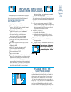
HIGHLY, MEGA-MONDO-
IMPORTANT: SOLO is
intended for more than just
“soloing.” It is THE way to
set levels for best noise and
headroom. Complete instructions on proper
level setting using SOLO are in Section 3: Gen-
eral Information, starting on page 20.
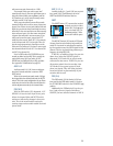
PHANTOM POWER
CAUTION: After switching PHANTOM Power on
or off, wait 1 minute before changing any mic/line
switch settings in that 8-channel block.
At the top of every eight channels is a PHAN-
TOM Power switch (7). Pressing it sends +48VDC
to the eight XLR sockets to the switch’s left. For in-
stance, depressing the PHANTOM switch above
Channel 8 sends phantom power to the XLRs on
channels 1 through 8. NOTE: It is always a good
idea to check with the Mic manufacturer to verify
phantom power requirements.
TRIM
The TRIM control (8) sets the gain of the input
amplifier for the MIC and LINE inputs. Proper setting
of the TRIM control is essential for good noise and
headroom performance. Trim pot settings may vary
widely depending upon the input level. The output of
different keyboards, drum machines, guitar effects
boxes, etc., vary from extremely weak to so hot that
they can practically be connected directly to speak-
ers. See pages 1, 20, or 25 for advice.
MIC/LINE SWITCH
Now we’ve jumped back to the top of the
strip. Sorry, but logically the input to the chan-
nel is the next thing to talk about. That’s
because it’s the source of the signal applied to
the channel fader and PAN control.