


15
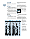
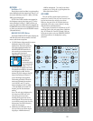
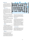
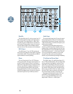
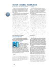
OUTPUT PANEL
The input and output jacks that cor-
respond to most of the functions in the
Output Panel are, logically, located in
the jack panel directly above the Output
Panel. The 8•Bus outputs to tape (and
the inputs from tape) are located on the
rear panel.
Submaster Inserts
At the top of the panel are the eight
Submaster Insert jacks (1). These
patch points allow you to insert a serial
processing device (such as a compres-
sor or an equalizer) into any of the
8•Bus submaster circuits. See Appen-
dix A for more details on using external
processing.
The insert point is after the summing amplifier,
but before the fader. Like the Channel Insert
points, the connectors are 1/4" TRS jacks, wired
unbalanced with the output or send signal on the
tip, the input or return signal on the ring, and the
sleeve common or ground.
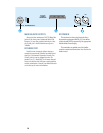
NOTE: These inserts can be used as pre-fader
direct outs, using an unbalanced (TS) 1/4” plug in
these two ways:
• Plugs are inserted just to the FIRST click.
There is no interruption of the signal; OR
• Plugs are inserted all the way in to the
SECOND click.This interrupts the signal
and routes it ONLY to the device you’re
sending to.
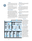
AUX Sends
The six AUX Sends (2) appear as six 1/4" jacks in
a row, just underneath the Sub Inserts.
AUX Sends 1 and 2 are balanced TRS outputs,
wired tip to high (+), ring to low (–), and sleeve to
ground. AUX Sends 1 and 2 are designed so that
1/4" unbalanced TS phone plugs can also be used,
with no loss of level. AUX Sends 3 through 6 are un-
balanced, with the tip high (+) and ring and sleeve
tied together as ground. Nominal level is +4dBu.
AUX Returns
The AUX Returns (3) are stereo, with a L&R in-
put for each return channel. Inputs are 1/4"
unbalanced jacks, nominal level (+4dBu).
One special feature: The Left input jack to each
return is also labeled “MONO.” If you have only one
return signal, plugging it into the “MONO/L” jack only
will cause it to be connected to both the left and
right return inputs and end up centered in your ste-
reo image. When a jack is plugged into the Right
input of the return, this mono feature is disabled: the
left input is fed to the left return, and the right input
is fed to the right return.
Main Inserts
On the upper right of the panel are two Main In-
sert jacks (4). These patch points allow you to insert
a serial processing device, such as a compressor or
an equalizer, into the Main L/R Mix. See Section 4 for
more details on using external processing.
The Main Insert’s insert point (try saying that fast
three times backward) is after the summing ampli-
fier but before the master fader. Like the Submaster
Insert points, the connectors are 1/4" TRS jacks,
wired unbalanced with the output or send signal on
the tip, the input or return signal on the ring, and the
sleeve common or ground.
Control Room Output
The two Control Room Output jacks (5) carry the
signal for the Control Room speakers. They are 1/4"
unbalanced, wired tip high, ring and sleeve ground.
Nominal level is +4dBu. This is where you connect
your control room monitor amplifier inputs.
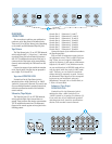
EXTERNAL
INPUT
MIX-B
OUTPUT
1
AUX SEND
1
R
L
2
2
R
R
3
3
R
L
4
4
R
R
5
5
R
L
6
6
R
R
L
7
L
L
R
8
R
R
R
SUBMASTER INSERT
AUX RETURN
CNTRL
RM OUTPUT
STUDIO
OUTPUT
MAIN MIX
MAIN
INSERT
2-TRACK
INPUT
123456
PHONES
12
(MONO)
L
(MONO)
L
(MONO)
L
(MONO)
L
(MONO)
L
(MONO)
(MONO) (MONO)
L
L
TIP = OUT RING = IN