


14
MZ-R909
Self-Diagnosis Result Display Mode
This set uses the self-diagnostic function system in which if an
error occurred during the recording or playing, the mechanism
control block and the power supply control block in the
microcomputer detect it and record its cause as history in the
nonvolatile memory.
By checking this history in the test mode, you can analyze a fault
and determine its location.
Total recording time is recorded as a guideline of how long the
optical pickup has been used, and by comparing it with the total
recording time at the time when an error occurred in the self-
diagnosis result display mode, you can determine when the error
occurred.
Clear both self-diagnosis history data and total recording time, if
the optical pickup was replaced.
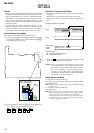
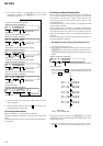
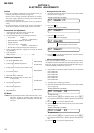
• Self-diagnosis result display mode setting method
1. Set the test mode (see page 12).
2. In the display check mode, turn the jog dial (down) or press the
[DISPLAY] key on the remote commander activates the self-
diagnosis result display mode where the LCD display as shown
below.
3. Then, each time the > key is pressed, LCD display descends
by one as shown below. Also, the LCD display ascends by one
when the
. key is pressed.
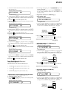
If the jog dial (down) is turned or the [DISPLAY] key on remote
commander is pressed with this display, the LCD switches to the
simple display mode.
4. Quit the self-diagnosis result display mode, and press
the x key to return to the test mode (display check mode).
5. The display changes a shown below each time the jog
dial (down) is turned or the [DISPLAY] key on the remote
commander is pressed.
However in the power mode (item number 700’s), only the
item is displayed.
6. Quit the manual mode, and press the
x key to return to the
test mode (display check mode).
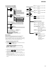
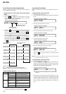
Overall Adjustment Mode
Mode to adjust the servo automatically in all items.
Normally, automatic adjustment is executed in this mode at the
repair.
For further information, refer to “Section 5 Electrical Adjustments”
(see page 18).
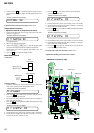
• Address & Adjusted Value Display
Remote commander LCD display
• Jitter Value & Adjusted Value Display
Remote commander LCD display
• Block Error Value & Adjusted Value Display
Remote commander LCD display
• ADIP Error Value & Adjusted Value Display
Remote commander LCD display
• Focus Drive Value & Adjusted Value Display
Remote commander LCD display
item number
address
adjusted value
item number
jitter value
adjusted value
item number
block error value
adjusted value
item number
ADIP error value
adjusted value
item number
focus drive value
adjusted value
011 C68S01
011 OFFJ01
011 063B01
011 059A01
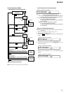
• Item Title Display
Remote commander LCD display
item number
item title
adjusted value
011 LrefPw 01
011 015F01
0XX 1 0000
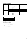
Remote commander LCD display
history code
Total recording time when error occurre
d
error display code
0XX 1 ****
0XX N ****
0XX N1****
0XX N2****
0XX R_****
1
1
XX
: Error code
****
: Total recording time