


19
MZ-R909
4. Turn the jog dial (up), or press the [PLAYMODE] key on the
remote commander.
(Turning the jog dial (up), or pressing the [PLAYMODE] key
on the remote commander causes the item number to be
switched to 762)
• Adjustment method of Vc PWM Duty (L)
(item number: 762)
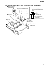
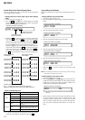
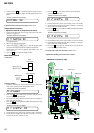
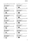
1. Connect a digital voltmeter to the AP914 (VC) on the MAIN
board, and adjust [VOL +] key (voltage up) or [VOL --] key
(voltage down) so that the voltage becomes 2.40 V.
2. Press the X key to write the adjusted value.
(The item number changes to 763 when X key is pressed)
Adjustment and Connection Location: MAIN board
(see page 20)
• Adjustment method of Vc PWM Duty (H)
(item number: 763)
1. Connect a digital voltmeter to the AP914 (VC) on the MAIN
board, and adjust
[VOL +] key (voltage up) or [VOL --] key
(voltage down) so that the voltage becomes 2.75 ± 0.015 V.
2. Press the
X key to write the adjusted value.
(The item number changes to 764 when X key is pressed)
Adjustment and Connection Location: MAIN board
(see page 20)
• Adjustment method of Vl PWM Duty
(item number: 764)
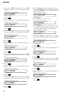
1. Connect a digital voltmeter to the AP915 (VL) on the MAIN
board, and adjust
[VOL +] key (voltage up) or [VOL --] key
(voltage down) so that the voltage becomes 2.30 V.
• Setting method of power supply manual adjustment
1. Make sure that the power supply voltage is 3V.
2. Set the test mode (see page 12).
3. Press the
. or [VOL--] key to activate the overall adjustment
mode.
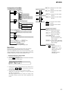
digital
voltmete
r
MAIN board
AP914 (VC)
AP912 (GND)
digital
voltmete
r
MAIN board
AP914 (VC)
AP912 (GND)
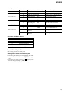
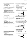
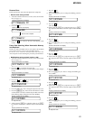
762 Vc1PWM **
Remote commander LCD display
**
: Adjusted value
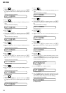
763 VchPWM **
Remote commander LCD display
**
: Adjusted value
7) Select the manual mode of the test mode, and set item number
863 (see page 13).
8) Adjust with the [VOL+] key (adjusted value up) or [VOL--]
key (adjusted value down) so that the adjusted value becomes
87.
9) Press the X key to write the adjusted value.
10) Select the manual mode of the test mode, and set item number
864 (see page 13).
11) Adjust with the [VOL+] key (adjusted value up) or [VOL--]
key (adjusted value down) so that the adjusted value becomes
39.
12) Press the X key to write the adjusted value.
13) Select the manual mode of the test mode, and set item number
865 (see page 13).
14) Adjust with the [VOL+] key (adjusted value up) or [VOL--]
key (adjusted value down) so that the adjusted value becomes
23.
15) Press the
X key to write the adjusted value.
16) Select the manual mode of the test mode, and set item number
866 (see page 13).
17) Adjust with the [VOL+] key (adjusted value up) or [VOL--]
key (adjusted value down) so that the adjusted value becomes
EC.
18) Press the X key to write the adjusted value.
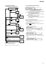
Power Supply Manual Adjustment
• Adjustment sequence
Adjustment must be done with the following steps.
1. Vc PWM Duty (L) adjustment (item number: 762)
r
2. Vc PWM Duty (H) adjustment (item number: 763)
r
3. Vl PWM Duty adjustment (item number: 764)
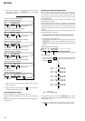
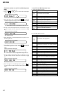
863 V2num **
Remote commander LCD display
**
: Adjusted value
864 V2dat **
Remote commander LCD display
**
: Adjusted value
+ 0.005
– 0.01
865 V3num **
Remote commander LCD display
**
: Adjusted value
866 V3dat **
Remote commander LCD display
**
: Adjusted value
Remote commander LCD display
000 Assy00
764 Vl PWM **
Remote commander LCD display
**
: Adjusted value
+ 0.005
– 0.01
digital
voltmete
r
MAIN board
AP915 (VL)
AP912 (GND)