


15
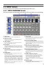
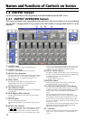
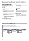
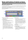
qf FADER select and qg OUTPUT fader
The qg OUTPUT fader has the two modes of ACTIVE and
INACTIVE.
To switch the fader mode, click the qf FADER select. The
selected mode lights in yellow. The yellow marker displayed
on the side of the fader indicates the fader position that is the
addition of the qg OUTPUT fader setup.
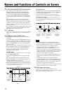
When the sound volume of a specific input channel is to be set
from the REMOTE screen and the GROUP FADER screen,
the fader position determined by the SRP-X700P Master
volume control and the remote control signal via the
REMOTE terminal is indicated.
ACTIVE mode:
ACTIVE mode is used to adjust the reference sound volume
by using SRP-X700P Manager.
You can adjust the qg OUTPUT fader by dragging the fader
portion.
The audio signal that has passed the INPUT fader on the
INPUT OVERVIEW screen and the OUTPUT fader on the
OUTPUT OVERVIEW screen, is output.
(The INPUT fader and the MASTER volume control of the
SRP-X700P, and REMOTE1 to 6 of the GROUP FADER
screen are bypassed. The sound volume of the output signal
increases by 5 dB in the case of Fig. 1. (Refer to page 10.))
INACTIVE mode:
INACTIVE mode is used to enable the INPUT fader and the
MASTER volume control of the SRP-X700P, and REMOTE1
to 6 of the GROUP FADER screen.
The sound volume is shown by the yellow marker that is
displayed on the side of the faders. The audio signal that has
passed all faders is output.
You cannot adjust the qg OUTPUT fader in INACTIVE mode.
(The sound volume of the output signal decreases by 25 dB in
the case of Fig. 2. (Refer to page 10.))
Note
• When the FADER select of the SRP-X700P Manager is
switched to ACTIVE for the first time after shipment from
the factory, the INPUT faders are all set to
–
∞ automatically
and the system is muted even if an attempt is made to
increase the sound volume using the INPUT fader or the
MASTER volume control of the SRP-X700P.
Muting is set in order to prevent the system from generating
a large sound abruptly when the FADER select is switched to
ACTIVE in the event of sound volume adjustment for the
first time. Entering muting is not a failure.
Therefore, do not terminate the SRP-X700P Manager or do
not disconnect the USB cable without adjusting the sound
volume.
• A sudden large sound may occur when you switch to
ACTIVE mode while the sound volume is reduced by either
the fader, MASTER volume or from the REMOTE terminal.
Before switching the mode, stop the connected equipments
and check the direction of the microphones.
• The mode of the INPUT fader and the mode of the OUTPUT
fader are interlocked and so are switched together.
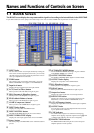
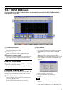
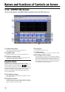
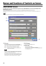
qh REC OUT index
Displays the index that is entered on the BLOCK screen.
qj REC OUT level meter
Displays the output signal level using the VU response.
qk REC OUT REF LEVEL selection box
You can set the reference output level for every output channel
on this selection box.
You can select –10, –5 or 0 dBu as the REC OUT level.
ql REC OUT MUTING button
Mutes output signals of the respective channels. The REC
OUT MUTING button lights in red when muted.
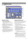
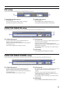
Power Amplifier Block
w; Operation mode setup box
Selects one of the following modes depending on the type of
speaker to be connected.
Lo Imp.: A low impedance (4 Ω to 16 Ω) speaker is to be
connected.
70 V LINE: A high impedance (32 Ω to 10 kΩ) speaker is to
be connected.
In the case of 70 V LINE, the channel 1 setup becomes valid
for the selectors and attenuators.
wa PROTECTION indicator
The PROTECTION indicator lights in red when the internal
power amplifier protection circuit operates.
Note
When the PROTECTION indicator lights
The protection circuit operates (PROTECTION indicator lights)
and the speaker and amplifier are protected from damage by
decreasing or cutting the output signal in case of the following:
• If the temperature of the heat sink inside the amplifier
exceeds the specified value.
The connected speaker impedance is too low.
Air intake and air exhaust holes (on the right and left sides of
the SRP-X700P) are choked by dust.
• The SPEAKER terminal is short-circuited.
In such a case, turn the POWER switch to the OFF position
and remove the cause of the fault before using the unit again.
• If DC voltage appears in the SPEAKER terminal due to failure.
Turn off the POWER switch and contact your Sony
representative where you purchased the unit or contact your
local Sony Sales office or Dealer.
ws SPEAKER OUTPUT index
Displays the index that is entered on the BLOCK screen.
wd SELECT setup box
Selects the input signal to the internal power amplifier. When
the 70V LINE is selected, the channel 1 setup only is valid.
wf ATT
Adjusts the output level for the internal power amplifier.
Clicking the [+] or [--] button increases or decreases the output
level in the range of 0 dB to ∞ dB. When the 70 V LINE is
selected, you can adjust channel 1 only. ATT is set at the
10 dB position for ordinary use.
wg SPEAKER OUTPUT MUTING button
Mutes the speaker output. The SPEAKER OUTPUT
MUTING button lights in red when muted. When the 70V
LINE is selected, the channel 1 only can be operated.
wh CLIP indicator
The CLIP indicator lights in red when the internal power
amplifier clips. Adjust the output level using wf ATT so that
the CLIP indicator does not light frequently.