


24
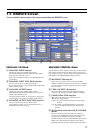
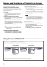
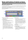
Connection to projector
For details of the method of connecting to a projector, see “System example when operating the SRP-X700P with the default setting when
shipped from the factory” of the SRP-X700P Operating Instructions.
When the RGB signal distributor to be connected to the projector, connect them as shown below.
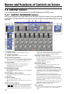
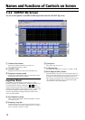
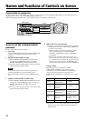
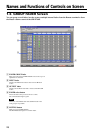
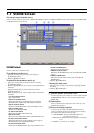
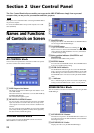
Names and Functions of Controls on Screen
OUTPUT
R/R-Y
VIDEO
S VIDEO
CONTROL S
IN
OUT
PROJECTOR CONTROL
OUTPUT
G/Y B/B-Y
SYNC/HD
VD
1
2
3
4
CONTROL-S
RS-232C
RGB
distributor
RGB
COMPONENT
S-VIDEO
VIDEO
RS-232C
Projector
SRP-X700P
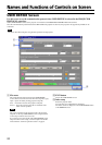
How to set the communication
protocol
Set the communication protocol as follows.
1. Port setup
Set the BITS PER SECOND setup box and the PARITY BIT
setup box in accordance with the specifications of the
projector.
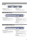
2. PROJECTOR POWER ON setup
1 Enter the PROJECTOR POWER ON command of the
projector, in the COMMAND setup box in which the
PROJECTOR POWER ON setup should be entered.
2 Set 60 seconds in the WAIT setup box. This will be finally
adjusted during the operation check.
Note
If the commands that can be received by the projector are
specified as ASCII code, convert the ASCII code to a
hexadecimal number and enter it in the COMMAND setup
box.
3. PROJECTOR POWER STANDBY setup
1 Enter the PROJECTOR POWER STANDBY command of
the projector, in the COMMAND setup box in which the
PROJECTOR POWER STANDBY setup should be
entered.
2 Set 100 seconds in the WAIT setup box. This will be finally
adjusted during the operation check.
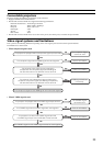
4. INPUT SELECT command setup
1 Select the respective signal formats using the signal format
select button and enter the command in the COMMAND
setup box as shown below.
• When the projector input can be selected by sending a
single command only, enter the INPUT SELECT
command in COMMAND1 and leave COMMAND2
unset (blank).
• When the two commands of both the signal system
select command and the input terminal select command
are required to select the input to the projector, enter the
signal system select command in COMMAND1 and
enter the input terminal select command in COMMAND2.
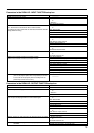
Setting example
When the signal systems of VIDEO, S-VIDEO,
COMPONENT and RGB are used, and when a single
command is required for the VIDEO and S-VIDEO input
selection while both commands are required for the
COMPONENT and RGB input signal selection, set as shown
below.
2 Set WAIT1 to 1 second and set WAIT2 to 9 seconds in the
WAIT setup box. This will be finally adjusted during the
operation check.
Signal system
VIDEO
S-VIDEO
COMPONENT
RGB
LAN
COMMAND1
VIDEO input terminal
select command
S-VIDEO input
terminal select
command
COMPONENT signal
select command
RGB signal select
command
Unset (blank)
COMMAND2
Unset (blank)
Unset (blank)
COMPONENT/RGB
input terminal select
command
COMPONENT/RGB
input terminal select
command
Unset (blank)