


01X Owner’s Manual
Overview of the 01X
27
Before UsingBasics SectionAppendix Getting StartedReference
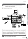
Mixer
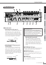
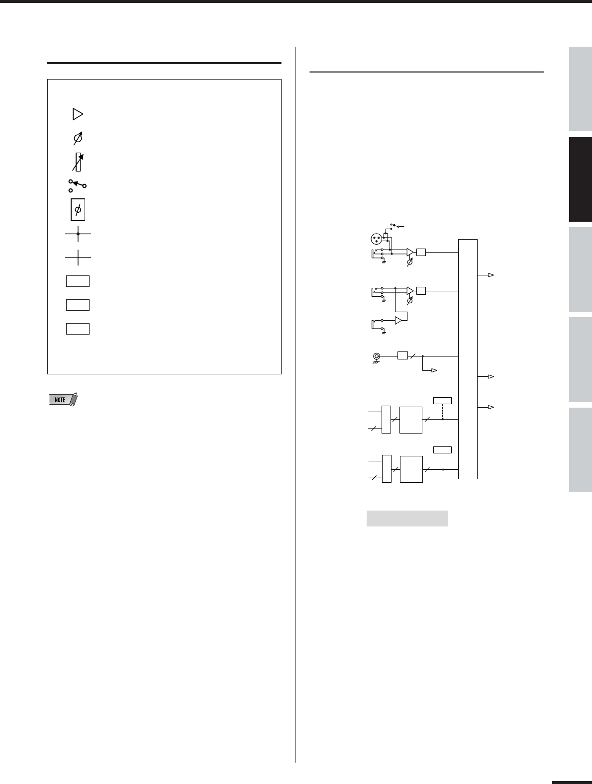
•For information on the entire signal flow of the 01X, refer to the Block
Diagram (at the end of this owner’s manual).
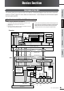
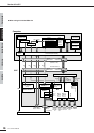
Getting Started (page 61)
Input patch Reference (page 88)
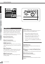
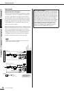
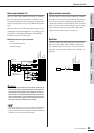
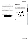
The Input Patch section allows assignment of input signals
to input channels 1 through 8 and stereo input channels
(STI) 1/2. The following types of input signals can be
selected.
•MIC/LINE INPUT 1-8
• DIGITAL STEREO IN
• EFFECT(FX)1/2
(Return signals from internal effects 1/2; ST IN only)
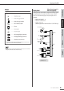
● Symbol Indications
.......... Amplifier stage
.......... Value change via knob
.......... Value change via fader
.......... On/off switch, button
.......... Phase
.......... Connected
.......... Unconnected
.......... AD (Analog/Digital) converter
.......... DA (Digital/Analog) converter
.......... Sampling rate converter
* Switches or faders connected with dotted line mean the set-
ting/value for one is linked to the other.
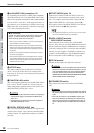
AD
DA
SRC
INPUT 1(...8)
ST IN 1(...2)
+48V
MIC/LINE INPUT
AD
INPUT
1/2
PHANTOM
LINE MIC
INPUT
3-8
Hi-z
INPUT 8 ONLY
LINE MIC
AD
DIGITAL STEREO IN
2
COAXIAL
SRC
EFFECT 1
AUX3
INSERT SEND
24
*1
SELECT
EFFECT
EFFECT 2
AUX4
INSERT SEND
24
*1
SELECT
EFFECT
INPUT SELECT (INPUT PATCH)
2 2
22
(to BUS CASCADE)
AD
1/2
AD
3-8
DIN-
L/R
FX1
FX2
METER
*3
(FX)
METER
*3
(FX)
EFFECT2 is available in
48kHz/44.1kHz mode only.
*1 Wordclock 96kHz/88.2kHz : 16
*3 Studio Manager only