


88
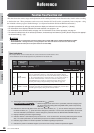
Function Tree/Function List
01X Owner’s Manual
Before Using Basics Section AppendixGetting Started Reference
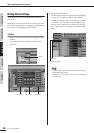
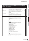
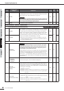
3 REMOTE AUTOMATION SETUP
u
FADER TOUCH
TIMEOUT
100 msec –
∞
Determines the amount of time that the 01X “waits” for fader movement
before turning off automation recording. This can be set over a range of 100
ms – 5000 ms, in 100 ms units. When a fader has not been moved for more
than the time set here, the 01X stops writing automation data. (This is also
referred to as “touch-out”; see page 15.) The [SEL] button flashes while auto-
mation writing is active (touch-in). When this parameter is set to “ ” (infin-
ity), there is no “time out” and writing continues indefinitely. You can
manually stop automation writing by pressing the [SEL] button when it is
flashing (page 17).
No 15
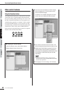
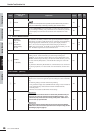
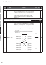
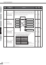
PATCH [UTILITY] → Channel knob 2
1 INPUT PATCH (IN1-4) (Input Channels 1 – 4)
2 INPUT PATCH (IN5-8) (Input Channels 5 – 8)
q
NONE/AD1 – 8/
DIN-L/DIN-R → IN1 – 8
Determines the input signal routing for input channels 1 – 8. This allows you
to route a specific hardware source (MIC/LINE INPUTS 1 – 8, or DIGITAL
STEREO IN L/R) to a desired channel input. Turning the knob immediately
changes the routing. The settings “AD1” – “AD8” correspond to MIC/LINE
INPUTS 1 – 8, while “DIN-L” and “DIN-R” correspond to the DIGITAL
STEREO IN signals. To disable input for the desired channel, select “NONE.”
• As the default setting, MIC/LINE INPUTS 1 – 8 are assigned to input
channels 1 – 8, respectively.
• The same input signal can be simultaneously routed to several different
input channels.
• The Input Patch settings made here can be stored to the Input Patch
Library (page 89).
No
27
61
e
e
No
t
No
u No
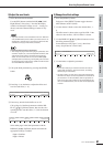
Knob
Function name/
settings
Explanation Prompt
Related
pages
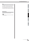
Block
diagram
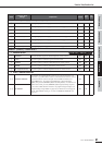
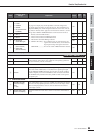
[PAGE SHIFT] + DISPLAY [ / ]
MIC/LINE INPUT jack
(AD1)
MIC/LINE INPUT jack
(AD2)
MIC/LINE INPUT jack
(AD3)
MIC/LINE INPUT jack
(AD4)
MIC/LINE INPUT jack
(AD5)
MIC/LINE INPUT jack
(AD6)
MIC/LINE INPUT jack
(AD7)
MIC/LINE INPUT jack
(AD8)
Input Channel 1
(IN1)
Input Channel 2
(IN2)
Input Channel 3
(IN3)
Input Channel 4
(IN4)
Input Channel 5
(IN5)
Input Channel 6
(IN6)
Input Channel 7
(IN7)
Input Channel 8
(IN8)
INPUT PATCH