


Control panel
6
M2500—Owner’s Manual
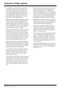
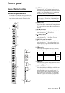
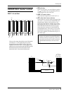
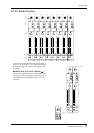
Stereo input channels
The M2500 provides four stereo input channels,
allowing line-level stereo sources such as sub-mixers,
effect processors, and CD players to be input. Of the
stereo input channels 1–4, channel 1 provides both
XLR and RCA phono input jacks, and you can select
and use one of these. Channels 2–4 provide a pair of
TRS phone input jacks. For this reason, there are
slight differences between the controllers of channel 1
and channels 2–4. Our explanation here will be based
on stereo input channel 1, and any differences for ste-
reo input channels 2–4 will be explained later.
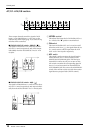
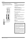
A
GAIN A
control
This adjusts the input sensitivity of the signal that is
input from the XLR connectors of the ST CH 1
INPUT A jacks (page 26). Levels of +10 dB to –30 dB
are supported. If the A/B select switch (
3
) is in the B
( ) position, this control will have no effect.
B
GAIN B
control
This adjusts the input sensitivity of the signal that is
input from the RCA phono connectors of the ST CH
1 INPUT B jacks (page 26). Levels of +10 dB to
–20 dB are supported. If the A/B select switch (
3
) is
in the A ( ) position, this control will have no
effect.
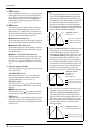
C
A
/
B
switch
This selects the input jacks that will be used for stereo
input channel 1. When the switch is in the upward
position ( ), the ST CH 1 INPUT A jacks can be
used. When the switch is in the downward position
( ), the ST CH 1 INPUT B jacks can be used.
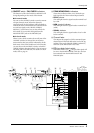
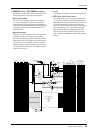
D
EQ controls
This is a two-band equalizer. The equalizer type, cen-
ter frequency, and gain range of each band is shown
below.
010
AUX14
+10 –30
A
+10 –20
–15 +15
B
A
B
HI
–15 +15
LO
GAIN
EQ
AUX1 PRE
PRE
PRE
010
010
010
010
010
010
010
010
010
010
010
010
010
010
AUX2
AUX3
AUX4
AUX5
AUX6
AUX7
AUX10
AUX11
AUX14
AUX13
AUX9
AUX8
PRE
AUX12
BAL
L
C
R
ODD EVEN
ON/EDIT
PFL
10
10
20
30
40
60
50
5
0
5
BAL
ST
LR
ODD EVEN
MONO
1-2
3-4
5-6
7-8
PEAK
NOM
SIGNAL
CHECK
ON
1
2
3
5
6
L
8
M
4
J
K
9
7
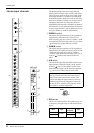
Note: Since stereo input channels 2–4 have only
one set of inputs, only one GAIN control is pro-
vided. (Nor is there an A/B select switch.) This
control will adjust the input sensitivity of the sig-
nal that is input from the TRS phone connectors
for the ST CH 2–4 INPUT jacks (page 26). Levels
of +10 dB to –30 dB are supported.
Band Type
Center
frequency
Gain
HIGH
Shelving
10 kHz
±15 dB
LOW 100 Hz
+10 –30
GAIN