


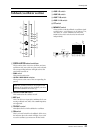


Rear panel
M2500—Owner’s Manual
29
L
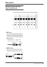
MIDI
connectors
These are standard five-pin MIDI connectors. By
connecting these to a sequencer or to the MIDI inter-
face of a computer, scenes can be selected from an
external device, or scene memories can be backed up.
●
MIDI IN connector
MIDI data is received at this connector. Use a MIDI
cable to connect this to the MIDI OUT connector of
your external MIDI device.
●
MIDI OUT connector
MIDI data is transmitted from this connector. Use a
MIDI cable to connect this to the MIDI IN connector
of your external MIDI device.
●
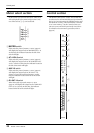
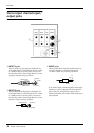
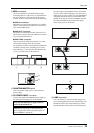
MIDI THRU connector
Data received at the MIDI IN connector is re-trans-
mitted without change from this connector.
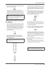
For example if you have connected three M2500 units
via MIDI as shown below, switching scenes on the
master M2500 (
1
) can cause the slave M2500 units
(
2
/
3
) to switch scenes in the same way.
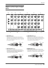
M
PHANTOM MASTER
switch
This is the master switch for the +48 V phantom
power supply.
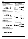
N
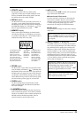
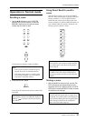
DC POWER INPUT
connector
Connect the supplied PW3000MA power supply to
this connector to supply power to the M2500.
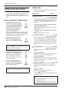
By connecting two PW3000MA units to the M2500
as shown in the following diagram, you can ensure a
stable supply of power. In this case, each PW3000MA
will supply 50% of the power to the M2500. In the
unlikely event that one of the PW3000MA units fail,
the other PW3000MA will automatically supply
100% of the power to the M2500.
O
LAMP
connector
This is an XLR-4-31 (four-pin female) output con-
nector that supplies power to the optional lamp. The
M2500-24/32 have two LAMP connectors, and the
M2500-40C/48C/56C have three LAMP connectors.
Note: The PW3000M power supply cannot be
used with the M2500 mixer.
Note:
Before connecting or disconnecting the
power supply cable, make sure that the power of
the PW3000MA is turned off.
1 2 3
PHANTOM
MASTER
DC POWER INPUT
READ OWNER’S MANUAL
OFF ON
N
M
DC POWER INPUT
DC PARALLEL INPUT DC OUTPUT
DC PARALLEL INPUT DC OUTPUT
LAMP
O