


Control panel
10 M2500—Owner’s Manual
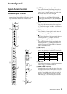
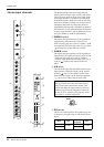
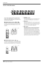
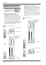
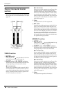
A7/G1–A14/G8 section
These output channels control the signals of AUX
buses 7–14 or GROUP buses 1–8. You can use the
GROUP/AUX FLIP switch (page 14) to select the sig-
nals that will be controlled.
■ GROUP/AUX FLIP switch= GROUP ( )
The signals of AUX buses 7–14 will be sent to chan-
nels A7/G1–A14/G8 respectively, and will be output
individually from the AUX/GRP OUT A7/G1–A14/
G8 jacks.
■ GROUP/AUX FLIP switch= AUX ( )
The signals of GROUP buses 1–8 will be sent to chan-
nels A7/G1–A14/G8 respectively, and output individ-
ually from the AUX/GRP OUT A7/G1–A14/G8 jacks.
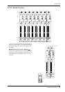
A LEVEL control
This adjusts the output level of AUX/GRP OUT A7/
G1–A14/G8. The “▲” position is nominal level.
B ON switch
This turns AUX/GRP OUT A7/G1–A14/G8 on/off.
When the switch is on ( ), the signals from the A7/
G1–A14/G8 section will be output from the AUX
OUT A7/G1–A14/G8 jacks respectively.
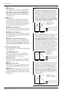
C AFL switch
This switch is used to monitor the signal from the
AUX/GRP OUT A7/G1–A14/G8 section via the
MONITOR OUT/PHONES jacks. If all the input
channel PFL switches are off, you can turn on this
AFL switch to monitor the corresponding signal of
the A7/G1–A14/G8 section from the MONITOR
OUT/PHONES jacks. You can use the MASTER PFL
switch of the monitor section to switch the monitor
signal between pre/post-fader (LEVEL control).
A7 / G1
AFL
LEVEL
010
ON
A8 / G2
AFL
LEVEL
010
ON
A9 / G3
AFL
LEVEL
010
ON
A10 / G4
AFL
LEVEL
010
ON
A11 / G5
AFL
LEVEL
010
ON
A12 / G6
AFL
LEVEL
010
ON
A13 / G7
AFL
LEVEL
010
ON
A14 / G8
AFL
LEVEL
010
ON
1
2
3
A7 / G1
AFL
LEVEL
010
ON
A8 / G2
AFL
LEVEL
010
ON
010
AUX5
AUX6
PRE
010
010
010
010
AUX7
AUX10
AUX9
AUX8
A7 / G1
AFL
LEVEL
010
ON
A8 / G2
AFL
LEVEL
010
ON
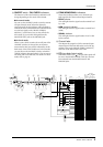
PAN
ST
L
C
R
ODD EVEN
MONO
LCR
1-2
3-4
5-6
7-8