


Control panel
M2500—Owner’s Manual 15
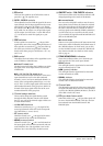
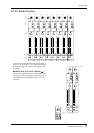
When you change the setting of the GROUP/AUX
FLIP switch, numerous functions of the output chan-
nels of GROUP buses 1–8 and AUX buses 7–14 will
change in addition to the faders. The functions avail-
able for the output channels of each bus are shown
below for each setting (GROUP/AUX) of the
GROUP/AUX FLIP switch.
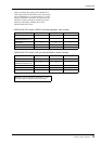
• GROUP/AUX FLIP switch= GROUP (principal application: main console)
• GROUP/AUX FLIP switch= AUX (principal application: monitor console)
Output channel GROUP buses 1–8 AUX buses 1–6 AUX buses 7–14
Master control 100 mm faders 100 mm faders Rotary faders
Channel assign switch
(MATRIX/ST/MONO/LCR)
❍✕✕
PAN control ❍✕✕
Mute switch ON/EDIT ON ON
INSERT I/O ❍❍✕
Output channel GROUP buses 1–8 AUX buses 1–6 AUX buses 7–14
Master control Rotary faders 100 mm faders 100 mm faders
Channel assign switch
(MATRIX/ST/MONO/LCR)
✕✕❍
PAN control ✕✕❍
Mute switch ON ON ON/EDIT
INSERT I/O ✕❍❍
Note: The output channels of AUX buses 1–6 are
not affected by the GROUP/AUX FLIP switch.