


Control panel
M2500—Owner’s Manual 9
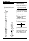
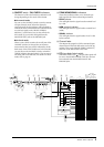
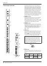
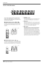
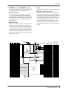
GROUP/AUX master section
AUX 1–6 section
These are the output channels that control the signals
of AUX buses 1–6. The signals that have passed
through these output channels will be output indi-
vidually from the AUX OUT 1–6 jacks (page 27). In
addition, they pass through the MONITOR MASTER
PFL/AFL buses and can be monitored from the
MONITOR OUT L/R and the PHONES jacks.
A ON switches
These turn AUX OUT 1–6 on/off. When a switch is
on ( ), the signal of the corresponding AUX bus
will be output to the AUX OUT jack.
B AUX 1–6 master faders
These adjust the output levels of AUX OUT 1–6.
C AFL (after fader listen) switches
These switches are used to monitor the signal of the
AUX OUT 1–6 section from the MONITOR OUT/
PHONES jacks. When an AFL switch is on (the
switch above the indicator will light), the pre/after-
fader signals of the AUX 1–6 section will be sent to
the MONITOR MASTER PFL/AFL buses respec-
tively, and can be monitored via the MONITOR
OUT/PHONES jacks. At this time, you can use the
MASTER PFL switch (page 19) in the monitor sec-
tion to select whether you will monitor the pre- or
after-fader signal.
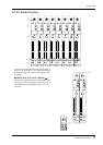
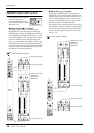
AUX1
AFL
ON
10
10
20
30
40
60
50
5
0
5
AUX2
AFL
ON
10
10
20
30
40
60
50
5
0
5
AUX3
AFL
ON
10
10
20
30
40
60
50
5
0
5
AUX4
AFL
ON
10
10
20
30
40
60
50
5
0
5
AUX5
AFL
ON
10
10
20
30
40
60
50
5
0
5
AUX6
AFL
ON
10
10
20
30
40
60
50
5
0
5
1
23
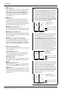
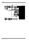
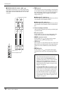
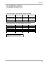
Note: If the PFL switch of even one input channel
is turned on, the signal of the MONITOR INPUT
bus will take priority for monitoring. In this case,
be aware that even if the AFL switch is turned on,
the MONITOR MASTER bus cannot be moni-
tored.
MONITOR
ST
LR
MONO
MONO
RL
ST
PFL AFL
ON
ON
(PFL)
to METER
INPUT
Same as AUX 1
AUX 2-6
AUX 1
1
INSERT I/O
0dB
AUX OUT
+4dB
ST
MASTER
LR
MONO
AFL
ON
AUX
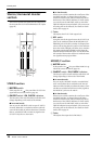
14
13
12
11
10
9
2
3
4
5
6
7
8
1
2 1
3