


Control panel
22 M2500—Owner’s Manual
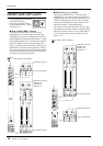
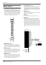
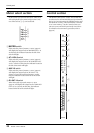
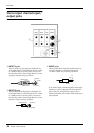
Meter select section
In this section you can select the source whose level
will be displayed by the meter bridge section. Only
one of the sources 1–4 can be selected.
A MATRIX switch
If this switch is pressed, meters 1/7–8/14 (page 24)
will display the output levels of MATRIX OUT 1–8.
At this time, the indicator located at the left of the
switch will light.
B A7-14/G1-8 switch
If this switch is pressed, meters 1/7–8/14 (page 24)
will display the output levels of AUX/GROUP OUT
A7/G1–A14/G8. At this time, the indicator located at
the left of the switch will light.
C AUX 1-6 switch
If this switch is pressed, meters 1/7–6/12 (page 24)
will display the output levels of AUX OUT 1–6.
(Meters 7/13 and 8/14 will not function.) At this
time, the indicator located at the left of the switch
will light.
D G1-8/A7-14 switch
When this switch is pressed, meters 1/7–8/14
(page 24) will display the output levels of GRP/AUX
OUT G1/A7–G8/A14. At this time, the indicator
located at the left of the switch will light.
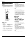
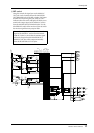
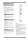
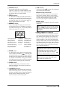
Control section
The M2500 is able to save “scenes“ that contain the
on/off status for each monaural/stereo input channel,
the G1/A7–G8/A14 section, the STEREO section, and
the MONO/C section. (This functionality is referred
to as “scene memory.”) In the Control section you
can save scenes, and recall a previously-saved scene.
(For details on scene memory procedure, refer to
page 30.)
G1-8/A7-14
AUX1-6
A7-14/G1-8
MATRIX
METER
SELECT
4
3
2
1
UTILITY
RECALL
MEMORY
STORE
CHECK
1 2
3 4
5 6
7 8
9
1
2
3
4
5
6
7
8
DIRECT
RECALL
CONTROL
0
ENTER
SCENE
MEMORY
4
5
3
2
1
8
7
6