


M2500—Owner’s Manual
3
Control panel
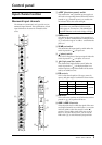
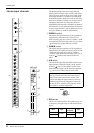
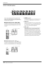
Input channel section
Monaural input channels
The M2500-24 {32/40C/48C/56C} provides 24 {32/
40/48/56} input channels. The specifications of each
input channel are the same for all models of the
series.
A
+48 V
(phantom power) switch
This switches the +48 V phantom power supply on/
off for the corresponding channel. When the switch is
pressed in ( ), phantom power is on. At this time
the indicator above the switch will light.
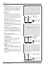
B
GAIN
control
This adjusts the input sensitivity. This control has a
range of –16 dB to –60 dB when the 26 dB pad switch
(
3
) is off, and a range of +10 dB to –34 dB when the
pad is on.
C
26 dB
pad switch
This attenuates the input signal by 26 dB. When the
switch is pressed in ( ), the pad is on.
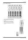
D
(phase) switch
This reverses the phase of the input signal. When the
switch is pressed in ( ), the phase is reversed.
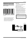
E
(high pass filter) switch
This switches the high pass filter on/off. When the
switch is pressed in ( ), the high pass filter is on,
and the frequency range below 80 Hz will be attenu-
ated by an 18 dB/oct curve.
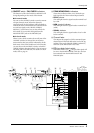
F
EQ
controls
This is a four-band equalizer. The type, center fre-
quency, and gain range of each band is shown below.
G
EQ
switch
This switches the equalizer on/off. When the switch is
pressed in ( ), the equalizer will be on.
H
AUX 1
–
AUX 14
controls
These adjust the level at which the signal of the mon-
aural input channel is set to AUX buses 1 to 14. Nom-
inal level (0 dB) is when the control is at the “
▲
”
position. The pre-fader signal will be sent to AUX
buses 1/2. For AUX buses 3 to 14, you can use the
PRE switch (
9
) to switch between pre/post fader.
+48V
GAIN
80
+10
26dB
–34
–16 –60
HI-MID
HI
–15 +15
–15 +15
400 8k
LO-MID
LO
EQ
AUX1 PRE
PRE
PRE
–15 +15
–15 +15
010
010
010
010
010
010
010
010
010
010
010
010
010
010
80 1.6k
AUX2
AUX3
AUX4
AUX5
AUX6
AUX7
AUX10
AUX11
AUX14
AUX13
AUX9
AUX8
PRE
AUX12
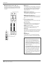
PAN
C
PAN
ST
L
C
R
ODD EVEN
MONO
LCR
ON/EDIT
PEAK
NOM
10
10
20
30
40
60
50
5
0
5
SIGNAL
CHECK
ON
1-2
3-4
5-6
7-8
PFL
010
AUX14
1
2
3
5
7
9
J
O
6
L
M
K
4
8
N
Note:
If you wish to use phantom power, make
sure that the rear panel PHANTOM MASTER
switch (page 29) is turned on. (The PHANTOM
MASTER indicator on the meter bridge will light.)
Band Type Center frequency Gain
HIGH Shelving 10 kHz
±15 dB
HIGH-MID Peaking 400 Hz to 8 kHz
LOW-MID Peaking 80 Hz to 1.6 kHz
LOW Shelving 100 Hz
80