


Control panel
M2500—Owner’s Manual 13
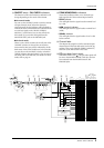
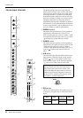
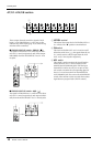
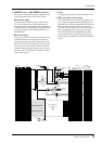
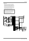
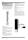
F ON/EDIT switch / ON, CHECK indicators
The function of this switch and these indicators will
change depending on the mode of the M2500.
● In normal mode
You can use the ON/EDIT switch to turn each G1/
A7–G8/A14 channel on/off. When the channel is
switched on/off, the ON indicator will be lit/dark to
indicate the status. Channels that are switched off will
not send any signals to the STEREO, MONO/C, or
MATRIX buses.
● In check mode
When a scene (which contains the on/off state of the
ON/EDIT switches) is selected, the on/off status
memorized in that scene will be indicated by the lit/
dark status of the CHECK indicator. In check mode,
you can also use the ON/EDIT switch to switch the
CHECK indicator between lit/dark. (The current on/
off setting will not be affected.) For details on check
mode, refer to page 32.
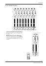
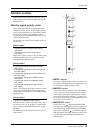
G Fader
This adjusts the output level of the GRP/AUX OUT.
H AFL (after fader listen) switch
This switch allows you to monitor the signal of the
G1/A7–G8/A14 section from the MONITOR OUT/
PHONES jacks. If the input channel PFL switches are
all off, turning this AFL switch on (the indicator
above the switch will light) will allow you to monitor
the corresponding G1/A7–G8/A14 section signal
from the MONITOR OUT/PHONES jacks. The
monitor signal can be switched between pre/post-
fader using the MASTER PFL switch of the monitor
section.
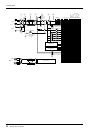
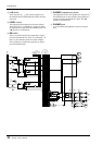
G7/A1
G1/A7
Same as
MONITOR
ST
LR
MONO
MONO
RL
ST
PFL AFL
ON
ON
(PFL)
to METER
to METER
from CPU
INPUT
GROUP/AUX FLIP
AUX
GROUP
MATRIX
and
and
AUX/GRP A8/G2-A14/G8
GRP/AUX G2/A8-G8/A14
G1/A7
A7/G1
G1/A7
0dB
INSERT I/O
AUX/GRP OUT
+4dB
GRP/AUX OUT
+4dB
ST
MASTER
LR
MONO
SUB IN
RLLR
MONO/C
STEREO
LR
MONO/C
STEREO
MATRIX
G8/A14
G7/A13
G6/A12
G5/A11
G4/A10
G3/A9
G2/A8
G1/A7
Control
ON/EDIT
CHECK
ON
LEVEL
ON
AFL
AFL
PA N
LCR
ST
MONO
AUXGROUP
14
13
12
11
10
9
2
3
4
5
6
7
88
7
6
5
4
3
2
11
6
1
2
3
8
5
4
7