


Control panel
M2500—Owner’s Manual 21
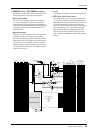
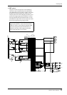
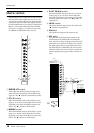
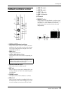
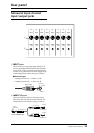
Talkback/oscillator section
A OSCILLATOR select switches
These switches select a test tone oscillator, and start
oscillation. Only one switch at a time can be selected.
The corresponding indicator will light to show the
switch that is turned on.
• PINK switch
This generates pink noise.
• 10 kHz/1 kHz/100 Hz switches
These generate a sine wave of the corresponding fre-
quency.
B OSCILLATOR ON switch
This switch turns the oscillator on/off.
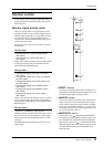
C MIC jack
This is an XLR-3-31 input jack (unbalanced) for con-
necting a talkback mic. Mics of 50–600Ω impedance
are supported.
D TB/OSC control
This adjusts the level of the talkback or oscillator.
E ON switch
This is an on/off switch for the talkback. If this is on,
the indicator above the switch will light. If you wish
to use the oscillator, you must turn off this switch.
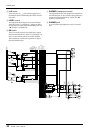
F AUX 1-2 switch
G AUX 3-6 switch
H AUX 7-10 switch
I AUX 11-14 switch
J ST switch
K MONO/C switch
These switches send the talkback or oscillator signal
to AUX buses 1–2, AUX buses 3–6, AUX buses 7–10,
AUX buses 11–14, the STEREO bus, and/or the
MONO/C bus. Each switch can be turned on/off
independently.
Note: The oscillator cannot be used together with
talkback. If you wish to use the oscillator, you must
turn off the talkback ON switch (5).
AUX11-14
MONO/C
ST
AUX7-10
AUX3-6
AUX1-2
ON
100Hz
1kHz
10kHz
PINK
ON
TALKBACK
OSCILLATOR
TB/OSC
MIC
010
6
7
8
9
J
K
1
5
4
3
2
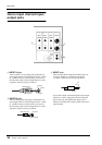
from CPU
MIC
TB/OSC
LR
MONO/C
STEREO
ON
AUX
14
13
12
11
10
9
2
3
4
5
6
7
8
1
5 4
3
KJ6789