


9
M-Module Installation
This manual provides the following information:
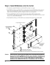
• Installing M-Modules in the E2251A Carrier including:
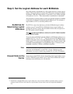
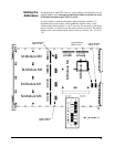
-- Setting Logical Addresses
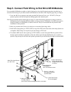
-- Attaching Field Wiring and Strain Relief
-- Installing RFI Dress Panels
• Installing the E2251A Carrier in a VXIbus Mainframe
• M-Module installation verification.
• Removing M-Modules from the Carrier.
For general information about the E2251A M-Module Carrier or for
M-Module programming information, refer to the E2251A M-Module
Carrier User’s Manual. For information about specific M-Modules, refer to
that M-Module’s User’s Manual. VXIplug&play drivers, downloadable
SCPI drivers, and Soft front panels are available on the CD ROM provided
with the Carrier and M-Modules. The E2251A does not support
MA-Modules.
WARNING SERVICE-TRAINED PERSONNEL ONLY. The information in this manual is for
service-trained personnel who are familiar with electronic circuitry and are aware
of the hazards involved. To avoid personal injury or damage to the instrument, do
not perform procedures in this manual or do any servicing unless you are
qualified to do so.
Caution All installation, wiring, and configuration procedures in this chapter are to be
done with power DISCONNECTED from the VXI mainframe and power
DISCONNECTED from any external wiring/cabling. To prevent equipment
damage, DISCONNECT the mainframe's power before installing any module into
the mainframe.
Caution STATIC ELECTRICITY. Static electricity is a major cause of component failure. To
prevent damage to the electrical components in the Carrier and the M-Modules,
observe anti-static techniques when installing or removing an M-Module from the
Carrier or installing or removing the Carrier from the VXI mainframe.
Caution Modules in Carrier slot M5 are restricted to 60Vdc, 30Vac
rms
, or 42Vac
pk
.
Caution Remove all packing material before installing Carrier in VXI mainframe.