


14
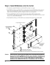
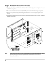
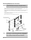
Step 4. Install M-Modules onto the Carrier
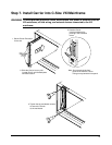
1. For internally-mounted M-Modules (slots M4 and M5) see Step 5, next page.
2. Install RFI Dress Panel (p.n. E2273-04301) on each of the front mounted M-Modules. Dress panels act
like a gasket and minimize RFI. Make certain the M-Module-to-Carrier connectors line up properly.
Make certain the M-Module standoffs are aligned over the screw mounting holes.
3. Secure each M-Module to the Carrier (from the back side) with four M3x5 mounting screws
(p.n. 0515-0372, with captive lock washer) supplied with M-Module. Open handles on Carrier to install
screws for slots M0 and M3 M-Modules.
4. Install blank Dress Panel (p.n. E2251-04301) over each unused front panel slot to minimize RFI.
Caution Static Electricity. Use anti-static techniques when installing/removing M-Module.
Use care when installing M-Modules onto the carrier connectors. The Carrier and
M-Module connectors ARE NOT keyed; it is possible to misalign an M-Module and
connect it to the wrong connectors. APPLYING POWER TO A MISALIGNED
M-MODULE WILL DAMAGE OR DESTROY THE M-MODULE AND THE CARRIER.
1. Install E2273-04301
Dress Panel on M-Module.
4. Install E2251-04301 Blank
Dress Panels on Empty Slots.
3. Secure M-Module with
four M3x6 screws.
2. Align M-Module on Carrier.
Do not remove
these screws
if removing
M-Module.
If necessary, slightly crimp Dress Panel with pliers so it stays attached to Carrier front panel.
0515-0430