


13
Setting the
Addresses
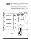
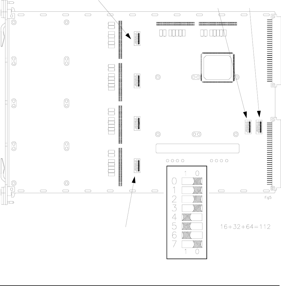
As shown below, the E2251A has six logical address switch banks, one for
each M-Module slot. You must set the logical address switches for each
M-Module installed in the E2251A Carrier.
A logical address switch bank contains eight individual switches. To
determine the logical address, add together the decimal values of the
switches that are set (position 1 = set, 0 = not set). For example, in the figure
below, switches 4, 5, and 6 are set, the other switches are not set. The logical
address is the sum of the decimal values of the set switches: 16 + 32 + 64 =
112.
M-Module M2
M-Module M1
M-Module M3
M-Module M0
M-Module M4
M-Module M5
Logical Address
Switch for M3
Logical Address
Switch for M0
Logical Address
Switch for M4
Logical Address
Switch for M5